
AN/FPS-90 Long-Range Height-Finder Radar
- Role
- Precision altitude measurement for targets acquired by a companion search radar
- Lineage
- Modified AN/FPS-6-family radar; mechanical variable nod removed, vertical nodding retained
- Documented service
- Conversions by 1962 to 1963; site-specific service into the 1980s
- Frequency and peak power
- S-band, 2,700 to 2,900 MHz; 5 MW peak in period technical sources
- Preservation
- No complete publicly preserved AN/FPS-90 installation confirmed
Designation and Common Name
AN/FPS-90 was the United States Air Force designation applied to selected AN/FPS-6-family long-range height-finder radars after a specific field modification removed the mechanical variable-nod mechanism from the antenna system. Air Defense Command's 1973 historical data states the relationship directly: application of TCTO 31P3-2FPS6-607, deleting variable nod from an AN/FPS-6B, changed the designation to AN/FPS-90. The period Air Force technical order is even more explicit. It says AN/FPS-90 nomenclature was assigned to AN/FPS-6 sets from which the mechanical variable-nod mechanism had been removed, while the variable-nod controls remained physically in place but were no longer used.
That definition matters because later summaries often describe the AN/FPS-90 simply as a "high-powered AN/FPS-6" or as if it were a clean-sheet replacement radar. The primary Air Force maintenance literature does not define it that way. It treats the AN/FPS-90 as a configuration within the AN/FPS-6 family and lists individual AN/FPS-6 serial numbers that had been redesignated. Almost all normal AN/FPS-6B maintenance references continued to apply to those radars except where the variable-nod mechanism was concerned. The designation therefore represents a controlled modification and configuration identity, not the birth of an unrelated radar architecture.
No official popular nickname has been found. Operators, maintenance personnel, Air Defense Command tables, and later station histories generally called the equipment the "FPS-90." Its identity was closely tied to the AN/FPS-6 because the two shared transmitter, receiver, indicator, antenna, tower, and maintenance lineage. The most useful plain-language description is therefore "AN/FPS-90 long-range height-finder radar," with the additional qualification that it was a modified AN/FPS-6-family system used to determine altitude after a search radar had found a target.
Equipment Type
The AN/FPS-90 was a fixed or transportable-to-site S-band height-finding radar designed for use with a long-range search radar of comparable coverage. It was not a continuously rotating search set. A search radar swept the horizon and supplied target range and azimuth. The height finder was then trained in azimuth toward a selected target and mechanically scanned its narrow beam through elevation. The resulting range-height display allowed an operator to determine the target's altitude and report that information to the local control room, a SAGE direction center, or another command-and-control element.
Period handbook terminology describes the AN/FPS-90 as a long-range, high-power, air-transportable height-finding radar. "Air-transportable" did not mean that the assembled radar was a lightweight tactical set that moved routinely with field units. The complete installation used a substantial antenna tower, operations-building equipment, waveguide, power distribution, and supporting plant. The term indicated that the equipment could be broken into transportable components for installation at a prepared site. In practice, most AN/FPS-90s served for years at permanent or semi-permanent Air Force radar stations.
The system supplied the third coordinate that two-dimensional long-range surveillance radars could not provide by themselves. A search set such as the AN/FPS-3, AN/FPS-24, AN/FPS-27, AN/FPS-66, or AN/FPS-67 could tell controllers that an aircraft was at a given bearing and range. The AN/FPS-90 answered the next operational question: how high was it? That answer was essential for threat evaluation, interceptor vectoring, deconfliction, and track quality in the SAGE and NORAD air-defense system.
Manufacturer and Development Lineage
The primary manufacturer identified in period technical documentation is General Electric Company, Heavy Military Electronics Department, Court Street, Syracuse, New York. The Air Force technical order covering AN/FPS-6, AN/FPS-6A, AN/FPS-6B, AN/FPS-90, and AN/MPS-14 identifies General Electric as the manufacturer of the AN/FPS-6 high-power height-finding family. MIL-HDBK-162A likewise identifies General Electric for the AN/FPS-90 and Canadian Marconi for the closely related Canadian AN/FPS-507. These contemporary sources provide the strongest manufacturing attribution for the equipment itself.
A later Air Combat Command historical study, Searching the Skies, describes the AN/FPS-90 as a Martin Marietta-produced high-powered version of the AN/FPS-6. That statement conflicts with the period General Electric technical order and handbook. The safest interpretation is not to erase either source. General Electric is retained as the documented manufacturer in the equipment master because it is supported by model-family technical literature. The Martin Marietta attribution is preserved as a retrospective-source conflict that still merits investigation, potentially involving later corporate responsibility, modification work, or the author's use of a secondary equipment summary.
The AN/FPS-90 grew from the AN/FPS-6, one of the defining height finders of the 1950s continental radar network. The basic family used a powerful S-band magnetron transmitter, a large mechanically steered reflector, a range-height indicator, and a nodding antenna that swept the vertical sector while operators tracked a target selected from an associated search radar. The AN/FPS-6A and AN/FPS-6B introduced changes within that lineage. The AN/FPS-90 retained enough commonality that the maintenance manual instructed technicians to use AN/FPS-6B procedures except where the deleted variable-nod mechanism created a real difference.
The technical order names equipment peculiar to the AN/FPS-90 while also showing how much remained common. The antenna group is OA-4540/FPS-90, and the reflector support is AB-776/FPS-90. The reflector itself is identified as AT-873/FPS-6B, demonstrating direct hardware continuity with the parent family. Transmitter, modulator, power-supply, receiver, indicator, synchro, and waveguide functions also remained rooted in the FPS-6 design. This is the clearest evidence that the AN/FPS-90 was a modified family member rather than a wholly independent radar.
Development and Service Dates
The AN/FPS-90 designation appears in Air Force technical literature by the early 1960s, and operational conversions were underway by 1962 and 1963. The Air Defense Command equipment tables repeatedly show AN/FPS-6 or AN/FPS-6A height finders becoming AN/FPS-90 during this period. Unit histories independently record the same pattern. Houma Air Force Station's FPS-6B became an FPS-90 in 1962, while Tonopah, Gettysburg, Baudette, and other stations record FPS-6-family conversions in 1963. The technical order's serial-number list confirms that redesignation was performed set by set rather than by declaring every existing FPS-6B an FPS-90.
The modification must also be understood against the larger SAGE-era modernization of the early 1960s. Search radars were gaining frequency diversity, anti-jam packages, and improved receivers. Direction centers increasingly depended on reliable digital radar reporting over large sectors. Height-finder accuracy therefore remained important even as the search system became more automated. Reusing the established AN/FPS-6 physical architecture through a controlled modification was cheaper and faster than replacing every height-finder installation with an entirely new radar.
There was no single service-retirement date for the AN/FPS-90. Some sets disappeared when individual Air Force stations closed in the late 1960s or early 1970s. Others remained at joint-use or strategically important sites into the 1970s and 1980s. At Makah Air Force Station, National Archives history records that the AN/FPS-90 was modified to AN/FPS-116 around 1977, and the resulting height finder remained until about 1988. Comparable JSS-era conversions occurred at other long-lived locations.
In Alaska, the retirement path was different. AN/FPS-90 height finders remained part of the Aircraft Control and Warning network paired with AN/FPS-93-family search radars until the SEEK IGLOO modernization introduced AN/FPS-117 three-dimensional radars in the 1980s. A modern 3-D search radar could provide range, azimuth, and height from one primary sensor, removing the operational need to cue a separate mechanically nodded height finder for every target. That technological transition, rather than one nationwide inactivation order, ultimately ended the AN/FPS-90 era.
Purpose and Operational Role
The AN/FPS-90 existed to turn an incomplete radar track into an altitude-qualified track. A two-dimensional search radar continuously scanned a broad azimuth sector and detected targets over long range, but its normal plan-position display did not provide precise altitude. Controllers therefore needed a second radar whose beam was optimized for vertical measurement. The height finder was pointed toward the search radar's target bearing, and its antenna swept through elevation until the target return could be placed accurately on a range-height display.
This division of labor was fundamental to Cold War air defense. The search radar had to survey a wide volume of airspace continuously. The height finder could concentrate on one selected bearing and use a much narrower vertical beam. That specialization improved altitude measurement without forcing the long-range search antenna to perform incompatible functions. A station with one search radar and two height finders could maintain surveillance while operators worked multiple tracks, especially during exercises or periods of heavy traffic.
The altitude number was operationally consequential. Interceptor controllers needed to know whether a target was high enough to threaten a particular sector, which fighter altitude and climb profile would be required, and whether multiple radar returns represented aircraft at different flight levels. SAGE computers could correlate target positions automatically, but the system still depended on sensor inputs. The AN/FPS-90 therefore supported the human and machine decision chain between first detection and an interceptor reaching the correct altitude to identify or engage a target.
The same capability had civil value. As military and FAA surveillance networks became more integrated, long-range search information was increasingly shared for air-route traffic control. Separate height-finder radars remained useful until secondary surveillance, improved air-traffic-control systems, and later three-dimensional primary radars reduced their importance. The AN/FPS-90's long service at selected joint-use sites reflects this overlap between national air defense and civil airspace surveillance.
Technical Specifications
The most authoritative period frequency specification located for the AN/FPS-90 is fixed-frequency operation in the 2700-2900 MHz range, within the S band. Both the Air Force technical order and MIL-HDBK-162A place the family in this band. The radar did not employ the multi-frequency search technique associated with large frequency-diversity surveillance radars. Its job was short-duration precision height measurement on a selected target bearing rather than continuous all-azimuth search.
Period technical documentation gives a peak RF output of 5 megawatts. The transmitter used the AN/FPS-6-family magnetron system, with the technical order identifying QK-338 or QK-338A transmitter tubes within the applicable configurations. Later popular summaries sometimes give 4.5 megawatts for an AN/FPS-90 "high-power" configuration and describe a receiver-mixer difference. Because the model-specific period technical order and federal handbook both give 5 megawatts and define the designation through the variable-nod modification, 5 megawatts is retained as the primary specification and the 4.5-megawatt narrative is treated as an unresolved secondary-source conflict.
The radar transmitted pulses approximately 2 to 3 microseconds long at a nominal pulse-repetition frequency between 300 and 400 pulses per second. The technical order's general performance table gives 2 plus or minus 0.1 microseconds for the family configuration, while MIL-HDBK-162A lists a 2-to-3-microsecond range for the AN/FPS-90 entry. These values should not be forced into a false single number because they reflect different source presentations and potentially different set configurations or adjustment limits.
No model-specific published average RF-output rating has been located in the primary material reviewed. A simple engineering calculation using 5 megawatts peak power, 2-to-3-microsecond pulses, and 300-to-400 pulses per second produces endpoint combinations of roughly 3 to 6 kilowatts average RF power. That number is useful for understanding duty factor, but it is a calculation rather than a published AN/FPS-90 rating. It must not be substituted for documented transmitter input power or total facility electrical demand.
MIL-HDBK-162A gives a model-specific range of 100 nautical miles. The same equipment entry describes indicator range scales extending to 100 and 200 miles, while broader AN/FPS-6-family summaries sometimes cite longer maximum ranges. These are different kinds of numbers. The 100-nautical-mile handbook value is retained as the model-specific operating-range statement. The 200-mile display scale shows what the indicator could present. Neither should automatically be converted into a claim that every AN/FPS-90 could determine height at 200 nautical miles against every target.
The handbook gives vertical coverage from minus 2 degrees to plus 32 degrees and horizontal coverage through 360 degrees by azimuth slewing. Height-display ranges extend to 75,000 feet, with several selectable scales for lower and intermediate altitude bands. The AN/FPS-6A family had documentation for a 100,000-foot scale, but that value should not be assigned automatically to the AN/FPS-90. The model-specific handbook entry supports 75,000 feet and an elevation-measurement accuracy of approximately 1,000 feet.
Resolution and accuracy data reinforce the radar's specialized role. MIL-HDBK-162A lists range accuracy at approximately plus or minus one percent, elevation accuracy in the form of about 1,000 feet, a vertical beamwidth of roughly 0.85 degree, azimuth resolution around 3.2 degrees, and elevation resolution around 0.90 degree. Those figures should be read as period handbook performance descriptors rather than a guarantee of identical real-world accuracy under every atmospheric, maintenance, target, and interference condition.
The system required substantial site power. The federal handbook lists 120/208-volt, three-phase, 60-hertz, four-wire AC service at about 50 kVA and states that the radar normally derived power from the same source that supplied the associated search radar. That common source simplified station utility design but also made dependable commercial or generator-backed electrical service important. A height finder was only useful if it could operate at the same time as the search radar that cued it.
Antenna and Scan Mechanics
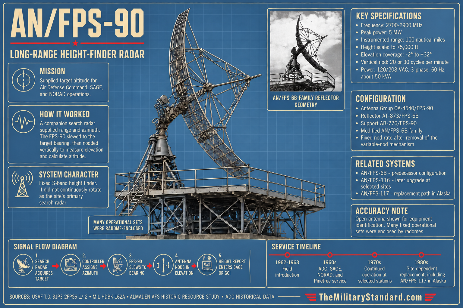
The AN/FPS-90 used the large AN/FPS-6B-family reflector architecture rather than a continuously spinning search antenna. The technical order identifies the OA-4540/FPS-90 antenna group, AB-776/FPS-90 reflector support, and AT-873/FPS-6B reflector. The reflector formed a narrow beam suitable for precision elevation work.
Azimuth motion placed the height finder on the bearing of the selected target. Once pointed in the correct horizontal direction, the antenna nodded through the vertical sector. The technical order describes slow and fast nod rates of approximately 20 or 30 cycles per minute. This motion moved the narrow beam repeatedly through elevation so a target return appeared on the range-height indicator as the beam crossed the aircraft.
The most easily misunderstood part of the AN/FPS-90 is the phrase "deleting variable nod." It did not mean the antenna ceased moving vertically. The technical order explicitly retains nod-rate controls and describes vertical scanning. What was removed was the mechanical variable-nod mechanism that allowed the nod arc to be changed. The variable-nod controls remained in place but were not used. The system therefore continued to function as a mechanically nodded height finder, but with the variable mechanical feature deleted from the designated configuration.
This distinction is operationally important. A height finder must scan elevation or otherwise form an elevation dimension. Saying that the AN/FPS-90 had "no nodding" would make its primary mission difficult to explain and would contradict the maintenance manual. The correct description is that AN/FPS-90 retained vertical nodding at established rates while eliminating the mechanical variable-nod function found in the parent configuration.
Transmitter and Receiver Characteristics
The transmitter was inherited from the AN/FPS-6 high-power S-band family. Its magnetron generated megawatt-class pulses that traveled through the duplexer and waveguide system to the antenna feed. After transmission, the radar rapidly switched the RF path so the receiver could listen for much weaker echoes returning from an aircraft. The enormous difference between transmitter pulse power and echo power required reliable duplexing and receiver protection.
The receiver chain used a balanced crystal mixer and a 726C reflex-klystron local oscillator, with a 30-MHz intermediate frequency identified in the technical literature. This superheterodyne arrangement converted the incoming microwave echo to a lower frequency where amplification, filtering, detection, and display processing were more practical. The design belongs to the vacuum-tube and microwave-tube era of the 1950s and 1960s, which explains the high maintenance burden compared with later solid-state radar.
The technical order lists anti-jamming and interference-control features including fast-time-constant, sensitivity-time-control, and anti-video-noise-limiter circuits. These functions helped manage clutter, strong nearby returns, and certain forms of interference. A later federal interference study involving an AN/FPS-90 in the Los Angeles area described the fielded radar as having a Dicke Fix operating mode. That later statement does not perfectly map onto the earlier maintenance-manual terminology and may reflect a specific receiver configuration or modernization state. Both are preserved rather than treated as interchangeable labels.
Operators worked with range-height indicators rather than a conventional search PPI alone. The family used long-persistence cathode-ray displays, range and elevation references, height counters, and synchro information tied to antenna position. A selected target could be followed as the antenna nodded. The operator aligned the display references with the target echo and read a derived height value, which could then be passed to the control system. The process required skill because clutter, multiple aircraft, weak echoes, and scan timing could complicate target identification.
How the System Worked
The operational sequence began with another radar. A long-range search set rotated continuously and displayed aircraft as range-and-azimuth plots. When a controller needed altitude on a particular track, the target bearing was sent to the height-finder position. In a SAGE station, automatic or semi-automatic cueing and station data systems reduced the need to pass every bearing by voice, but the basic logic was unchanged. The AN/FPS-90 was told where to look horizontally.
The height finder then slewed to that azimuth. Unlike the search radar, it did not need to keep sweeping all 360 degrees while measuring height. Its antenna concentrated energy into the target bearing and nodded vertically from below the horizon to the upper elevation limit. The target was illuminated as the beam crossed its elevation angle. On the range-height indicator, slant range formed the horizontal relationship and antenna elevation established the vertical geometry needed to determine altitude.
The operator's task was to make sure the correct echo was being measured. Search-radar range gave a strong reference. The RHI displayed the selected sector in a side-view geometry, allowing the operator to distinguish a target from ground clutter and to follow its return through successive nods. Height counters and display marks then converted the geometry into a usable altitude report. In high-traffic or exercise conditions, a station with multiple height finders could divide targets between operators.
Atmospheric refraction and Earth curvature affected the relationship between radar line of sight and actual height. Height-finder systems therefore depended on calibrated geometry, station elevation, range, and operating procedures rather than simply reading the antenna elevation angle as the aircraft's altitude. This is one reason dedicated height finders remained large and carefully maintained instruments even after the basic concept was well understood.
The radar's narrow beam and high peak power supported long-range measurements, but a successful height report still depended on target radar cross section, propagation, clutter, jamming, operator workload, and the search radar's ability to maintain the track. The AN/FPS-90 was one element in a sensor team. Its performance cannot be reduced to a single maximum-range number without losing the operational relationships that made the system useful.
SAGE, NORAD, and Data-System Integration
The AN/FPS-90 served during the mature SAGE period, when local radar stations were increasingly connected to large computerized direction centers. SAGE did not make the height finder obsolete. It made timely and correctly identified altitude data more valuable because the computer could combine range, azimuth, height, identification, speed, and track history from multiple inputs into a common air-defense picture.
MIL-HDBK-162A specifically lists the AN/FST-2 coordinate data transmitting set as related equipment used with AN/FPS-90 and AN/FPS-507 installations. The AN/FST-2 family digitized radar information for transmission to SAGE direction centers. At the station level, this meant the FPS-90's height report could become part of a machine-supported track rather than remaining only a local scope operator's observation.
NORAD integrated these station reports across sectors and national boundaries. Canadian Pinetree sites operated the related height-finder architecture, and U.S. Air Force-operated stations in Newfoundland and Labrador received AN/FPS-90s during 1960s modernization. ADC data records FPS-90 at Stephenville, Melville/Goose Bay, Cartwright, and Hopedale in this overseas network. These deployments demonstrate that the equipment was not limited to the continental United States.
The AN/FPS-90 also appeared in Air Defense Command's mobile-radar program and later "Z" site tables. The word mobile can be misleading because many of these stations evolved into substantial fixed facilities. The designation referred to the program and equipment lineage used to fill geographic gaps and expand coverage, not to a radar that was routinely packed up after each mission. Once installed on a tower with an operations building and utilities, an FPS-90 functioned as part of a stable regional air-defense network.
Typical Installation and Physical Layout
An AN/FPS-90 installation normally occupied a dedicated antenna tower close enough to the operations building and companion search radar to share power, communications, maintenance, and control functions. MIL-HDBK-162A identifies the temperate AB-25B/FPS-6 and arctic AB-259/FPS-6 tower families. The handbook also describes site-area requirements, including a level circular area of roughly 30 feet diameter for a temperate tower and a substantially larger area for the arctic installation. These dimensions describe immediate tower requirements, not the acreage of an entire radar station.
The antenna and pedestal occupied the tower top, while transmitter, receiver, indicator, and control equipment were distributed between tower-associated spaces and the operations building. Waveguide carried high-power RF between the transmitter and antenna. Electrical distribution, cooling and ventilation, test equipment, maintenance benches, spare parts, and intercommunications were essential. A height finder that could not hold frequency, beam alignment, synchro calibration, or display geometry would produce unreliable altitude data even if its antenna still moved.
At many sites the antenna was enclosed in a radome. The radome protected the reflector, feed, drive system, and personnel from wind, ice, precipitation, and severe weather while allowing microwave energy to pass. Arctic and mountain sites particularly benefited from weather protection. The familiar white spherical or faceted radomes of Cold War stations therefore concealed very different sensor types. A search radar radome and an FPS-90 height-finder radome might stand near one another but perform fundamentally different tasks.
The operations building typically brought the search and height-finder functions together. Search operators and data technicians identified tracks, while height-finder operators received target assignments and returned altitude. SAGE communications equipment, AN/FST-2 data-transmission hardware, telephone and radio circuits, and local control consoles connected the sensor room to the sector direction center. Maintenance shops kept magnetrons, klystrons, CRTs, synchros, motors, gear trains, blowers, and power supplies operating continuously.
Station infrastructure extended well beyond the radar tower. Remote radar sites required generators, commercial-power interfaces where available, fuel storage, access roads, snow removal, water and sewage systems, barracks or family housing at isolated locations, motor pools, administrative buildings, and security. The AN/FPS-90's physical footprint must therefore be understood at two scales: the radar equipment itself occupied a tower and operations spaces, while its reliable 24-hour mission depended on the larger Air Force station around it.
Deployment Across the Permanent and Mobile Radar Networks
Air Defense Command records show the AN/FPS-90 spread widely across the United States during the 1960s. The equipment appeared at long-established permanent-system stations, mobile-program stations that matured into fixed sites, and later SAGE "Z" sites. Representative locations included Wadena and Baudette in Minnesota, Dickinson in North Dakota, Gettysburg in South Dakota, Lewistown and Kalispell in Montana, Tonopah and Winnemucca in Nevada, Keno and Burns in Oregon, Almaden in California, Houma in Louisiana, and Fort George G. Meade in Maryland.
The deployment pattern reflects the radar's role as a companion sensor rather than a standalone network. Sites usually paired it with a long-range search radar. At Almaden, the AN/FPS-90 worked alongside the massive AN/FPS-24 frequency-diversity search radar. At Houma and Keno it was associated with AN/FPS-67-family search equipment. At Gettysburg it supported an AN/FPS-66 search radar. At other locations it stood beside AN/FPS-7, AN/FPS-27, AN/FPS-35, or ARSR-family sensors.
Some stations operated two FPS-90 height finders. Air Defense Command tables show paired FPS-90s at sites including Burns, Winnemucca, Tonopah, Dickinson, Thomasville, and Key West during particular periods. Two height finders increased the station's ability to service multiple targets and reduced the operational impact of maintenance downtime. Later force reductions often removed one of the pair before the station itself closed.
The Air Defense Command tables also show how quickly equipment configurations changed. A 1963 snapshot may list two FPS-90s, while a later column records one removed in 1967 or 1969. Another station may show the FPS-90 surviving after a search-radar replacement. This is why site evidence must be date-specific. A single list of "radars at the station" can accidentally combine equipment that never operated together.
Pinetree Line and Northeastern Service
The AN/FPS-90 contributed to the U.S.-Canadian air-defense network through stations in Newfoundland and Labrador. Air Defense Command's overseas tables record FPS-90 modernization at Stephenville, Melville/Goose Bay, Cartwright, and Hopedale. These stations had originally operated earlier FPS-3, CPS-6, FPS-502, TPS-502, and related equipment before receiving later search and height-finder sets.
Canadian radar-history material similarly identifies FPS-90 service at Cartwright from approximately 1964 to 1968, Hopedale from approximately 1963 to 1968, Stephenville during the 1960s, and Goose Bay in the same general modernization period. The specific dates vary by source and whether a date means installation, operational acceptance, or a table snapshot. The Air Defense Command source is retained as the primary source-control record while specialist Canadian documentation supplies useful local context.
Cold, wind, icing, remoteness, and difficult supply lines made these northern deployments demanding. The arctic tower and radome architecture existed because antenna alignment and drive machinery could not be left exposed to severe weather without consequences. The continued use of large mechanically scanned height finders in this environment demonstrates both the importance of altitude data and the maintenance commitment required to keep the network functioning.
These northeastern sites also illustrate the international structure of NORAD. The sensor could be U.S.-designed and operated by U.S. Air Force personnel on Canadian soil while its data supported a binational defense command. The AN/FPS-90 was therefore part of a network whose operational geography crossed the political boundary between the United States and Canada long before modern integrated airspace surveillance became routine.
Southern Air Defense System
The AN/FPS-90 remained useful in the southern United States even as the original continental network contracted. Aerospace Defense Command's Southern Air Defense System table dated 1973-04-12 lists an FPS-90 height finder at Ellington Air Force Station, Texas, paired with an ARSR-1 search radar. This is a particularly useful late snapshot because it demonstrates the system surviving beside a civil-derived long-range search radar rather than only with its original 1950s Air Force search partners.
The southern network had to watch approaches over the Gulf of Mexico and Caribbean while operating in an environment of heavy civil aviation and significant federal radar overlap. Key West likewise used paired height finders during modernization of its long-range search capability. These sites foreshadowed the later Joint Surveillance System model in which military and FAA needs increasingly converged on shared long-range radar locations.
The Ellington example also shows why a height finder could outlive several generations of search equipment. The station's search sensor could change while the FPS-90 remained a useful altitude-measurement tool. Equipment replacement was therefore modular. A radar site did not always replace every antenna and electronics suite at once. Commanders and engineers retained working subsystems until mission, supportability, or a new 3-D radar made them unnecessary.
FAA and Joint Surveillance System Longevity
By the 1970s and 1980s, many Air Force radar sites were moving toward joint military-civil operation or full FAA responsibility. The Joint Surveillance System formalized the use of shared long-range radar data for both air defense and air traffic control. The AN/FPS-90 was not itself the central long-range search sensor in that system, but selected height finders survived at locations where the underlying search radar and site remained operationally important.
The AN/FPS-116 became the key late-life bridge. Federal spectrum documentation describes the AN/FPS-116 as essentially an upgrade package for AN/FPS-6 and AN/FPS-90 height-finder radars. At Makah, the National Archives records the AN/FPS-90 conversion to AN/FPS-116 around 1977. Site histories for Malmstrom, Odessa-Andrews, and other locations describe comparable transitions. The old antenna towers and much of the mechanical architecture could therefore continue in service while electronics and processing were modernized.
This extended life should not be mistaken for technological stasis. A radar carrying an FPS-90 lineage in 1980 could differ substantially from a 1963 configuration after receiver, display, drive, and data-interface changes. The equipment master therefore treats AN/FPS-116 as a replacement or upgrade path rather than claiming that untouched original FPS-90 electronics remained universally operational until the late 1980s.
The end came when three-dimensional surveillance became practical and supportable at the required scale. A 3-D radar could produce range, azimuth, and height directly, eliminating the separate cue-measure-report cycle of a height finder. In a network concerned with lower operating costs and fewer remote personnel, removing a second large antenna, transmitter, receiver chain, and operator position offered major savings.
Alaska and SEEK IGLOO
Alaska retained the two-radar search-and-height-finder architecture longer than many continental sites because of its geography and strategic warning role. Historical documentation describes AN/FPS-93-family search radars paired with AN/FPS-90 height finders at Alaskan Aircraft Control and Warning stations during the 1960s and 1970s. These radars watched northern air approaches under some of the harshest operating conditions in the Air Force.
The SEEK IGLOO program replaced this labor-intensive architecture with AN/FPS-117 three-dimensional minimally attended radars in the 1980s. Alaska's official aircraft-control history describes AN/FPS-117 activation during the 1984-1985 period. A contemporary MITRE study characterized SEEK IGLOO as a modern long-range 3-D radar developed to replace the outmoded and expensive-to-maintain AN/FPS-93 search and AN/FPS-90 height-finder equipment.
This replacement is a clean illustration of technological evolution. The older station needed one radar to search and another to determine height, plus operators and maintenance technicians for both. The AN/FPS-117 electronically formed multiple beams and produced three coordinates from one modern sensor. The result reduced personnel and maintenance while improving the network's ability to handle targets automatically.
Alaska also demonstrates why late-retirement dates must be qualified by site. An AN/FPS-90 could be gone from one continental station in 1968 while still serving an Alaskan warning site well into the 1980s. The equipment's national history is therefore a sequence of local retirements driven by station closure, conversion, or modernization rather than one ceremonial end date.
Interference and Electronic-Environment Experience
Height finders operated in increasingly crowded radio-frequency environments. A federal interference investigation in the Los Angeles region documented an AN/FPS-90 receiving interference associated with an ASR-7 airport-surveillance radar. The interference appeared during portions of the FPS-90's nodding cycle and was associated with specific antenna bearings and low elevation angles. The study is valuable because it shows the practical vulnerability of a high-power military radar receiver to another legitimate radar sharing nearby spectrum.
The report described the affected AN/FPS-90 as having a Dicke Fix operating mode. The 1960s technical order separately lists fast-time-constant, sensitivity-time-control, and anti-video-noise-limiter functions. These statements should not be combined into a fictional single package without knowing the exact field configuration and date. The equipment changed over a long career, and a receiver at one site could have been modified after the original technical order.
The interference case also illustrates the difference between hostile jamming and peacetime electromagnetic compatibility. The AN/FPS-90 was part of a national defense network built with anti-jam features, but it still had to coexist with civil and military radars operating nearby. Frequency assignment, antenna siting, receiver selectivity, operating procedures, and interagency coordination were therefore part of keeping the radar useful.
These problems became more important as FAA and military systems shared sites and airspace. A radar could not simply increase power to solve every interference problem because the neighboring system might then experience greater interference in return. Engineering coordination, filters, receiver modifications, operating-frequency planning, and eventual modernization were the sustainable solutions.
Variants and Modification Relationships
AN/FPS-90 itself is best treated as a configuration within the AN/FPS-6 family. The defining public technical statement is the deletion of the mechanical variable-nod mechanism under TCTO 31P3-2FPS6-607. The Air Force technical order lists a large set of specific FPS-6 serial numbers that received the AN/FPS-90 designation, demonstrating controlled conversion rather than a blanket renaming of the entire FPS-6B fleet.
AN/FPS-507 was a closely related Canadian height finder. MIL-HDBK-162A groups AN/FPS-90 and AN/FPS-507 in the same equipment entry while identifying Canadian Marconi as manufacturer of the latter. The relationship is close enough to share many characteristics, but the designations should remain distinct. A Canadian AN/FPS-507 should not be entered automatically as an AN/FPS-90 site simply because the systems were related.
AN/FPS-116 was a later upgrade path applied to AN/FPS-6 and AN/FPS-90 height finders. Federal technical literature characterizes it as an upgrade package rather than an unrelated new tower. At long-lived JSS sites, the FPS-116 designation marks a meaningful modernization boundary. Histories should therefore record the conversion date where known rather than treating an FPS-90 as continuously unchanged through the end of height-finder service.
AN/FPS-117 was different. It was not a modification of the FPS-90. It was a new three-dimensional phased-array radar that could replace both the long-range search and separate height-finder functions in Alaska. The distinction matters because the transition from FPS-90 to FPS-116 represents life extension of the older architecture, while FPS-117 represents replacement of the architecture itself.
Systems it Replaced / Systems that Replaced it
At most conversion sites, the AN/FPS-90 directly replaced the previous identity of an AN/FPS-6, AN/FPS-6A, or particularly AN/FPS-6B that had undergone the approved modification. The physical transition could therefore be subtler than a new radar arriving on trucks. A familiar tower, reflector family, and much of the electronics remained, but modification status and nomenclature changed. This is why station histories often say an FPS-6 was "modified to" or "upgraded to" an FPS-90.
At some sites the AN/FPS-90 was later replaced by a different conventional height finder such as the AN/FPS-26A, particularly when frequency diversity or other capabilities justified a new set. At other locations, one of a pair of FPS-90s was simply removed as the threat and workload declined. A station could therefore pass through several mixed configurations before closure.
The most important late-life replacement path was AN/FPS-116 modernization. This kept the basic height-finder concept alive within the Joint Surveillance System period. The eventual retirement of AN/FPS-116 around 1988 at several long-lived sites effectively closed the AN/FPS-6/FPS-90 lineage in operational U.S. air defense.
In Alaska, SEEK IGLOO and AN/FPS-117 replaced both the search and height-finder pairing. Elsewhere, newer 3-D search radars and improved civil surveillance made separate height finders unnecessary. The final successor was therefore not one universal model but a new system concept in which altitude came from the primary three-dimensional radar or other integrated surveillance sources.
Operational History
Wadena Air Force Station in Minnesota is representative of the conversion era. Air Defense Command data records the station with AN/FPS-64-family search equipment, AN/FPS-6, and AN/FPS-90 in the 1960s. Specialist station history says the FPS-6A was modified to FPS-90 in 1963 and that the radar was removed later in the decade. The sequence shows how a relatively new height finder could have a short local life because site configuration and force structure changed rapidly.
Baudette Air Force Station, also in Minnesota, provides a clearer unit-level story. Its radar squadron history records one FPS-6 upgraded to FPS-90 in 1963. The station also operated an AN/FPS-24 search radar and AN/FPS-26A height finder. The FPS-90 remained part of the mixed sensor suite until the later drawdown, illustrating the common practice of keeping different height-finder types together for capacity and redundancy.
Tonopah Air Force Station in Nevada operated two AN/FPS-90s after conversion from FPS-6-family sets. Air Defense Command tables show the pair in the 1960s and later record one being removed. The high desert location gave the radar a broad horizon, but isolation increased the importance of reliable utilities, spare parts, and maintenance. The station's equipment sequence also demonstrates that "two FPS-90s" describes a particular period, not a permanent fact for the life of the station.
Houma Air Force Station in Louisiana shows the FPS-90 working with a modernized search radar. Unit history records the site's FPS-6B being upgraded to FPS-90 in 1962, while the long-range search mission later used AN/FPS-67-family equipment. The station was inactivated around 1970. Its short post-conversion life illustrates the strategic contraction that could make technically useful radar equipment surplus before its physical service life was exhausted.
Gettysburg Air Force Station in South Dakota paired an AN/FPS-66 search radar with AN/FPS-90 height finding during the SAGE period. This combination joined an ECCM-improved long-range search radar with a mature S-band altitude sensor. It represents the modular nature of Air Defense Command modernization: the search radar could receive one family of anti-jam upgrades while the height finder followed its own development path.
Almaden Air Force Station in California provides unusually good photographic and architectural evidence. Its historic resource study documents the AN/FPS-90 in Building 107 beside the far larger AN/FPS-24 search-radar complex. A 1960s photograph in that study shows the FPS-24 and FPS-90 installations together. The study reports that the FPS-90 remained until roughly June 1980, making Almaden a valuable example of the radar's later continental service.
Makah Air Force Station in Washington is one of the best documented long-life sites. National Archives history states that by 1963 the 758th Radar Squadron operated an AN/FPS-7A search radar with AN/FPS-90 and AN/FPS-26A height finders. Around 1977 the FPS-90 was modified to AN/FPS-116. The AN/FPS-116 remained until about 1988, when the staffed Air Force radar station closed and the FAA assumed the continuing radar mission.
Fort George G. Meade's radar complex in Maryland retained an AN/FPS-90 alongside AN/FPS-67-family search equipment during the 1960s. Air Defense Command tables record changes in the number of height finders as the station evolved. Surviving foundation and tower-remnant photographs help show how the sensor stood within a much larger military electronics landscape that also included Army air-defense command systems in the Fort Meade area.
Key West's southern-defense installation used paired FPS-90s during part of its 1960s configuration. The site watched the Florida Straits and Caribbean approaches and later evolved toward joint-use radar. The timing requires care. Key West's radar station played a prominent role in southern air defense during the Cuban Missile Crisis, but the evidence reviewed for this page does not establish that the AN/FPS-90 configuration itself was fully operational during the October 1962 crisis. The radar should therefore not be assigned a dramatic crisis role without site-specific date evidence.
Ellington Air Force Station in Texas preserves a late official snapshot. Aerospace Defense Command's 1973 Southern Air Defense System table pairs an ARSR-1 search radar with an FPS-90 height finder. This arrangement demonstrates that the FPS-90 remained operationally relevant after the disappearance of many classic Air Force search-radar types and could work alongside a radar architecture closely associated with civil air-route surveillance.
Alaskan Aircraft Control and Warning stations extended the mission into the 1980s. Their FPS-90s worked in remote, severe-weather environments where radar coverage of northern approaches was strategically important. SEEK IGLOO's replacement of the FPS-93/FPS-90 pairing with AN/FPS-117 became one of the clearest examples of 3-D technology eliminating a separate height-finder function rather than merely substituting one height-finder model for another.
Known Installations
- The following list is representative rather than a claim of a final production total. Air Defense Command tables, unit histories, and later station documentation show that equipment moved, was modified, and was sometimes reduced from two sets to one. Dates and variant states should therefore be retained with each installation relationship.
- Wadena Air Force Station, Minnesota - AN/FPS-6A-family height finder modified to AN/FPS-90 in the early 1960s; later removed during station modernization.
- AN/FPS-24 search and AN/FPS-26A height-finder equipment.
- Sweetwater Air Force Station, Texas - AN/FPS-90 recorded in Air Defense Command mobile-program equipment tables.
- AN/FPS-24 search radar; historic study places removal about June 1980.
- AN/FPS-66 search and AN/MPS-14 height-finder equipment during the early 1960s.
- AN/FPS-24 search radar.
- Burns Air Force Station, Oregon - two AN/FPS-90s documented during part of the 1960s configuration.
- Houma Air Force Station, Louisiana - AN/FPS-6B upgraded to AN/FPS-90 in 1962; station later inactivated.
- AN/FPS-66 search radar during part of the SAGE period.
- Tonopah Air Force Station, Nevada - two FPS-6-family sets converted to AN/FPS-90; one later removed before station closure.
- AN/FPS-66 search radar.
- Lewistown Air Force Station, Montana - AN/FPS-90 documented with AN/FPS-3A and AN/FPS-6A equipment before later reductions.
- Kalispell Air Force Station, Montana - paired AN/FPS-90s documented with AN/FPS-7B search radar during part of the 1960s.
- AN/FPS-67-family search and AN/FPS-6A height-finding equipment.
- AN/FPS-27 and AN/FPS-6A equipment.
- Dauphin Island Air Force Station, Alabama - AN/FPS-90 documented in a mixed long-range radar suite during SAGE-era operations.
- Thomasville Air Force Station, Alabama - paired AN/FPS-90 height finders documented during part of the station's operational period.
- AN/FPS-24 and AN/FPS-26A equipment.
- Key West Air Force Station / Naval Air Station Key West radar site, Florida - two AN/FPS-90 height finders documented during part of the southern-defense configuration.
- AN/FPS-67-family search radar; former height-finder foundations and tower remains photographed.
- Ellington Air Force Station, Texas - AN/FPS-90 paired with ARSR-1 in the 1973 Southern Air Defense System table.
- Makah Air Force Station, Washington - AN/FPS-90 in service by 1963 and modified to AN/FPS-116 around 1977.
- Bucks Harbor Air Force Station, Maine - AN/FPS-90 documented in later station service and retained into the long joint-use period.
- Malmstrom Air Force Base radar site, Montana - AN/FPS-90 lineage later modified to AN/FPS-116 during JSS-era modernization.
- Odessa-Andrews FAA / JSS radar site, Texas - AN/FPS-90 documented in the 1970s and later converted to AN/FPS-116.
- Stephenville Air Station, Newfoundland - AN/FPS-90 documented in Air Defense Command overseas-network modernization.
- Melville / Goose Bay Air Station, Labrador - AN/FPS-90 documented in the later Pinetree-era radar suite.
- Cartwright Air Station, Labrador - AN/FPS-90 documented during the mid-1960s modernization period.
- Hopedale Air Station, Labrador - AN/FPS-90 documented during the 1960s before later inactivation.
- AN/FPS-93-family search equipment before SEEK IGLOO.
- Other Alaskan Aircraft Control and Warning sites - AN/FPS-90s were used at multiple northern stations before replacement by AN/FPS-117 three-dimensional radars; each site requires date-specific confirmation before a permanent cross-link is made.
Preserved Examples / Surviving Equipment
No complete, intact, publicly displayed AN/FPS-90 installation has been confirmed in the research for this page. This is not surprising. The radar was a distributed system consisting of a large antenna and pedestal, transmitter and receiver equipment, indicators, power supplies, waveguide, tower, environmental systems, and site infrastructure. Preserving the full system would require maintaining a substantial building-scale artifact rather than placing one cabinet in a museum.
Former radar sites preserve more useful physical evidence. Fort George G. Meade has documented foundations and remains associated with former height-finder towers. Almaden's historic resource study records Building 107 as the AN/FPS-90 location and preserves photographs of the radar in its operational context. Makah retains major portions of the old station landscape even though the radar equipment itself has been replaced. Similar tower bases and modified structures survive at other former SAGE stations.
A Canadian memorial at Sioux Lookout preserves an AT-873/FPS-6B reflector, the same reflector family identified in the AN/FPS-90 technical order. It is not documented as a preserved AN/FPS-90 set and should not be presented as one. It is nevertheless a valuable surviving artifact for understanding the scale and shape of the antenna hardware shared by the family.
Technical manuals are a major form of preservation for this equipment. T.O. 31P3-2FPS6-2-1 preserves component nomenclature, block diagrams, maintenance procedures, waveforms, antenna-control details, receiver circuits, and the serial-number redesignation list. MIL-HDBK-162A preserves a compact federal equipment entry with performance, power, installation, and associated-system data. Together these documents allow the AN/FPS-90 to be reconstructed historically even where the physical radar has disappeared.
Technical Conflicts and Source Safeguards
The Almaden historic resource study contains a building-number conflict. Its narrative identifies the AN/FPS-6A height finder upgraded to AN/FPS-90 as Building 107 and identifies the AN/MPS-14 as Building 108. Figure 15 also labels the AN/FPS-90 as Building 107, but the Figure 12 caption calls it Building 108. This history follows the narrative and Figure 15, treating the Figure 12 caption as an apparent error rather than silently combining the two radar towers.
The first major conflict is manufacturer attribution. Period technical documentation identifies General Electric as the AN/FPS-6-family manufacturer and specifically places AN/FPS-90 in that technical-order family. MIL-HDBK-162A also gives General Electric for AN/FPS-90. Searching the Skies, a later official Air Force historical study, attributes the FPS-90 to Martin Marietta. General Electric is retained in the master record because it is supported by contemporary technical evidence, while the Martin Marietta statement is preserved in the verification queue for further research rather than silently deleted.
The second conflict is the common "high-power version" description. Primary documents give 5 megawatts peak power and define the FPS-90 nomenclature by removal of the mechanical variable-nod mechanism. Several later summaries give 4.5 megawatts and describe a receiver-mixer or high-power distinction. The page does not average those figures or combine them. The 5-megawatt primary-source rating controls the specification field, and the later 4.5-megawatt narrative remains a source conflict pending discovery of the original change document that produced it.
The third issue is range terminology. MIL-HDBK-162A gives 100 nautical miles. The indicator system includes scales extending to 200 miles, and general FPS-6-family summaries often cite still longer maximum range. A display scale is not automatically an instrumented or reliable target-height range, and a parent-family maximum is not automatically a model-specific FPS-90 figure.
The fourth issue is the meaning of "variable nod removed." The phrase can be misread as eliminating vertical scan. The technical manual itself resolves the issue by continuing to specify nodding operation at 20 or 30 cycles per minute while stating that the mechanical variable-nod mechanism was removed. The FPS-90 continued to nod. What disappeared was the variable mechanism and its operational control function.
The fifth issue is the anti-jam receiver description. The technical order lists FTC, STC, and AVNL circuits. A later federal interference report says the specific AN/FPS-90 under study had a Dicke Fix operating mode. The page treats these as date- and configuration-sensitive evidence. It does not claim every FPS-90 simultaneously had one universal anti-jam package throughout its service life.
Legacy
The AN/FPS-90 represents the mature form of the classic two-radar continental air-defense station. One large antenna searched continuously. Another large antenna concentrated on selected targets and measured their altitude. The arrangement required buildings, operators, maintenance personnel, data links, and substantial power, but it gave SAGE and NORAD the three coordinates needed to build useful tracks before modern 3-D primary surveillance radar was widely available.
Its service history also demonstrates the value of controlled modification. Rather than discard the AN/FPS-6 family when requirements changed, the Air Force altered existing sets and assigned a new configuration designation. The equipment retained proven mechanical and microwave architecture while removing a feature the Air Force no longer needed. That approach conserved money, shortened modernization time, and preserved common maintenance knowledge across a large installed fleet.
The long route from AN/FPS-90 to AN/FPS-116 and then to modern 3-D systems charts a broader technological transition. The first step retained the mechanically nodded height-finder architecture and improved it. The second step replaced the architecture with one radar that could search and measure height automatically. This reduced the number of antennas and people required at remote sites and changed the physical appearance of the continental radar network.
The system also leaves an architectural legacy. Former height-finder towers, radomes, access roads, operations buildings, and foundations remain at many Cold War radar stations even when the equipment is gone. Correctly identifying which tower carried an FPS-90 helps reconstruct how a station worked. The history of an air-defense site is not only the history of its search radar. The height finder was the instrument that turned a two-dimensional detection into a usable altitude-qualified threat track.
Chronology
- 1950s General Electric AN/FPS-6-family height finders became a principal altitude-measurement component of the expanding continental air-defense radar network.
- 1961-03-15 The basic issue date of T.O. 31P3-2FPS6-2-1 placed the AN/FPS-6 family in a common Air Force maintenance framework that later included the AN/FPS-90.
- 1962 Houma Air Force Station's AN/FPS-6B was upgraded to AN/FPS-90 according to unit-history documentation.
- 1962 Air Defense Command overseas-network modernization began placing AN/FPS-90s at selected Newfoundland and Labrador stations.
- 1963 Air Force technical-order changes documented the AN/FPS-90 nomenclature and listed serial-numbered AN/FPS-6 sets redesignated after removal of the mechanical variable-nod mechanism.
- 1963 Wadena Air Force Station's AN/FPS-6A-family height finder was modified to AN/FPS-90.
- 1963 Baudette Air Force Station received an AN/FPS-90 conversion in its SAGE-era equipment suite.
- 1963 Tonopah Air Force Station operated two AN/FPS-90 height finders following FPS-6-family conversion.
- 1963 Gettysburg Air Force Station operated AN/FPS-90 with AN/FPS-66 search radar in the SAGE network.
- 1963 Makah Air Force Station operated AN/FPS-90 and AN/FPS-26A height finders with an AN/FPS-7A search radar.
- 1963 Air Defense Command equipment tables recorded paired AN/FPS-90s at several mobile-program and permanent-network stations.
- 1963 Almaden Air Force Station's AN/FPS-90 served beside the AN/FPS-24 frequency-diversity search radar.
- 1963 Fort George G. Meade's radar site used AN/FPS-90 in a mixed search-and-height-finder configuration.
- 1963 Dickinson Air Force Station was documented with AN/FPS-66 search radar and two AN/FPS-90 height finders.
- 1963 Lewistown Air Force Station was documented with AN/FPS-3A, AN/FPS-6A, and AN/FPS-90 equipment.
- 1963 Kalispell Air Force Station was documented with AN/FPS-7B and two AN/FPS-90 height finders.
- 1963 Keno Air Force Station was documented with AN/FPS-67, AN/FPS-6A, and AN/FPS-90 equipment.
- 1963 Burns Air Force Station was documented with AN/FPS-7B and two AN/FPS-90 height finders.
- 1963 Winnemucca Air Force Station was documented with AN/FPS-66 and paired AN/FPS-90s.
- 1963 Eufaula Air Force Station was documented with AN/FPS-24, AN/FPS-90, and AN/FPS-26A.
- 1964 Cartwright, Hopedale, Stephenville, and Goose Bay-area Pinetree stations were operating or receiving AN/FPS-90-family modernization during the mid-1960s.
- 1964 Key West's radar equipment tables record paired AN/FPS-90 height finders during southern-defense modernization.
- 1965 Force-structure reductions began removing some duplicate AN/FPS-90s while retaining one height finder at selected stations.
- 1966 Several permanent-network equipment tables continued to list AN/FPS-90 height finders as station organizations and companion search-radar configurations changed around them.
- 1968 Multiple SAGE radar stations with AN/FPS-90 equipment closed during continental air-defense reductions.
- 1969 Several sites reduced paired AN/FPS-90 installations to one set or removed the height finder entirely.
- 1970 Houma Air Force Station ended operations after several years of AN/FPS-90 service.
- 1970-09-30 Tonopah Air Force Station inactivated after its late period with AN/FPS-90 height finding.
- 1971 Baudette and other northern stations continued AN/FPS-90 operations into the early 1970s despite broader ADC reductions.
- 1973-04-12 Aerospace Defense Command's Southern Air Defense System table listed an AN/FPS-90 height finder paired with ARSR-1 at Ellington Air Force Station, Texas.
- 1973 Historical Data of the Aerospace Defense Command formally summarized AN/FPS-90 as an AN/FPS-6B changed by TCTO 31P3-2FPS6-607 deleting variable nod.
- 1977 Makah Air Force Station modified its AN/FPS-90 to AN/FPS-116 at approximately this time.
- Late 1970s Selected JSS and joint-use sites converted AN/FPS-90-family equipment to AN/FPS-116 while many other stations retired separate height finders.
- 1980-06 Almaden Air Force Station removed its AN/FPS-90 at approximately this time according to the site's historic resource study.
- 1983 The Joint Surveillance System era increasingly shifted continental surveillance toward shared FAA and Air Force search radars while retaining some upgraded height finders.
- 1983 Federal technical reporting described AN/FPS-116 as an upgrade package for AN/FPS-6 and AN/FPS-90 height finders.
- 1984-1985 SEEK IGLOO began activating AN/FPS-117 three-dimensional radars at Alaskan sites, replacing AN/FPS-93 / AN/FPS-90 pairings.
- 1988 Makah's AN/FPS-116, descended from its AN/FPS-90, was retired at approximately the time the staffed Air Force radar station closed.
- 1988 Separate FPS-6/FPS-90-family height finders disappeared from several remaining JSS locations as three-dimensional surveillance reduced the need for them.
- 1990s FAA-operated long-range radar sites continued reusing many Cold War towers and mountaintops after the AN/FPS-90 electronics had been removed.
- 2011-03-09 The Former Almaden Air Force Station Historic Resource Study preserved photographic and architectural documentation of the AN/FPS-90 installation.
- 2020-10-27 The National Archives published a detailed history of Makah Air Force Station documenting AN/FPS-90 and later AN/FPS-116 service.
- Present No complete publicly preserved AN/FPS-90 installation has been confirmed, but shared-family antenna artifacts, technical manuals, photographs, foundations, and former height-finder towers preserve the system's history.
Photographs and diagrams
- U.S. Air Force Technical Order T.O. 31P3-2FPS6-2-1: Technical manual containing AN/FPS-6 / AN/FPS-90 antenna, control, transmitter, receiver, waveguide, and maintenance diagrams.
- MIL-HDBK-162A / TM 11-487C-1: Federal radar-equipment handbook with the AN/FPS-90 / AN/FPS-507 equipment entry, component list, performance data, and installation information.
- National Archives, A Front Line of Defense: The 758th Radar Squadron and the Makah Air Force Station: Illustrated station history with USAF and archival images of Makah Air Force Station, where AN/FPS-90 served by 1963 and later became AN/FPS-116.
- Former Almaden Air Force Station Historic Resource Study: Historic resource report containing a 1960s photograph identifying the AN/FPS-90 installation at Building 107 beside the AN/FPS-24 complex.
- Online Air Defense Radar Museum, AN/FPS-6 equipment page: Photographs and equipment material for the parent AN/FPS-6 height-finder family whose hardware formed the basis of AN/FPS-90.
- Online Air Defense Radar Museum, Fort Meade recent photographs: Photographs of the former Fort Meade radar complex, including height-finder tower foundations and radar-site remnants associated with the FPS-90 era.
- Online Air Defense Radar Museum, Tonopah Air Force Station: Site photographs and equipment history for a station that operated two AN/FPS-90 height finders during part of the 1960s.
- Online Air Defense Radar Museum, Wadena Air Force Station: Site photographs and history for Wadena, where an FPS-6-family height finder was modified to AN/FPS-90.
- Online Air Defense Radar Museum, Key West radar site: Photographs and site-history material for the southern radar station that operated paired AN/FPS-90 height finders during part of its Cold War service.
- Online Air Defense Radar Museum, Odessa-Andrews FAA site: Photographs and site history for a long-lived Texas radar location where AN/FPS-90 was later modernized to AN/FPS-116.
- C&E Museum / Pinetree Line, AN/FPS-90: Equipment photographs and Canadian Pinetree-line deployment information for AN/FPS-90 height finders.
- Veterans Affairs Canada, Sioux Lookout Memorial: Photographs of the preserved AT-873/FPS-6B reflector, useful for understanding the shared antenna family used by AN/FPS-90, but not documented as a preserved FPS-90 set.
- Saratoga Radar Site: Photographs and historical material from a former SAGE radar station that operated AN/FPS-90 in its mixed sensor suite.
- Flickr, Almaden AFS AN/FPS-90-era radar image: Community-hosted historical image showing the Almaden radar complex during the FPS-90 / FPS-24 period; use with attribution and verify image metadata before publication.
Information sources (21)
- PDFU.S. Air Force, T.O. 31P3-2FPS6-2-1, Service, Radar Sets AN/FPS-6, AN/FPS-6A, AN/FPS-6B, AN/FPS-90 and AN/MPS-14
SOURCE FOR: Primary source for the formal AN/FPS-90 designation definition, General Electric family attribution, serial-number conversions, nodding system, transmitter, receiver, antenna components, and maintenance architecture.
- PDFDepartment of Defense, MIL-HDBK-162A / TM 11-487C-1
SOURCE FOR: Primary federal handbook source for AN/FPS-90 frequency, peak power, pulse parameters, 100-nautical-mile range statement, elevation limits, accuracy, beamwidth, electrical requirements, towers, and associated AN/FST-2 system.
- PDFHeadquarters Aerospace Defense Command, Historical Data of the Aerospace Defense Command, 1946-1973
SOURCE FOR: Primary source for the ADC definition of AN/FPS-90 as an FPS-6B modified by TCTO 31P3-2FPS6-607 and for representative installation evidence across the permanent, mobile, overseas, and Southern Air Defense networks.
- PDFDavid F. Winkler, Searching the Skies: The Legacy of the United States Cold War Defense Radar Program
SOURCE FOR: Official Air Force historical study providing AN/FPS-6/FPS-90 program context and the retrospective Martin Marietta / high-power description preserved as a conflict against period General Electric technical documentation.
- WEBNational Archives, A Front Line of Defense: The 758th Radar Squadron and the Makah Air Force Station, Neah Bay, Washington, 1950-1988
SOURCE FOR: Official archival history documenting Makah's 1963 AN/FPS-90 service, circa-1977 conversion to AN/FPS-116, 1988 retirement, station facilities, SAGE role, and photographs.
- PDFPage & Turnbull, Former Almaden Air Force Station Historic Resource Study
SOURCE FOR: Historic-resource source for Almaden's AN/FPS-90 installation, Building 107, the AN/FPS-24/FPS-90 physical relationship, removal around 1980, and a period photograph.
- PDFAlaska Department of Natural Resources, History of the Aircraft Control and Warning System in Alaska
SOURCE FOR: Official state historic source for the Alaskan FPS-93/FPS-90 radar era and the 1980s SEEK IGLOO conversion to AN/FPS-117.
- WEBMITRE / Department of Defense, SEEK IGLOO technical reporting
SOURCE FOR: Technical source describing AN/FPS-117 as a modern long-range three-dimensional replacement for outmoded, maintenance-intensive AN/FPS-93 search and AN/FPS-90 height-finder equipment in Alaska.
- PDFNational Telecommunications and Information Administration, NTIA Report 83-117
SOURCE FOR: Federal technical source identifying AN/FPS-116 as essentially an upgrade package for AN/FPS-6 and AN/FPS-90 height-finder radars.
- PDFNational Telecommunications and Information Administration / Office of Telecommunications, Report 76-97
SOURCE FOR: Federal interference-study source documenting operational interference affecting an AN/FPS-90, the radar's nodding geometry, and the field report's Dicke Fix receiver-mode terminology.
- PDFU.S. Air Force Unit History, 657 Radar Squadron
SOURCE FOR: Unit-history source for Houma Air Force Station, including the AN/FPS-6B to AN/FPS-90 upgrade and later station inactivation.
- PDFU.S. Air Force Unit History, 692 Radar Squadron
SOURCE FOR: Unit-history source for Baudette Air Force Station, including the 1963 AN/FPS-90 conversion and its relationship to the site's AN/FPS-24 and AN/FPS-26A equipment.
- PDFU.S. Air Force Unit History, 866 Radar Squadron
SOURCE FOR: Unit-history source for Tonopah Air Force Station, including two AN/FPS-90 height finders and later reduction of the pair.
- PDFU.S. Air Force Unit History, 903 Radar Squadron
SOURCE FOR: Unit-history source for Gettysburg Air Force Station and its AN/FPS-66 / AN/FPS-90 SAGE-era sensor configuration.
- PDFU.S. Air Force Unit History, 801 Radar Squadron
SOURCE FOR: Unit-history source for Malmstrom's radar mission and the late AN/FPS-90 to AN/FPS-116 modernization path.
- WEBC&E Museum / Pinetree Line, AN/FPS-90 equipment entry
SOURCE FOR: Specialist Canadian radar-history source for FPS-90 equipment identity and deployment dates at Cartwright, Goose Bay, Hopedale, and Stephenville.
- WEBTown of Machiasport, Points of Interest / Bucks Harbor Air Force Station
SOURCE FOR: Local-government source for Bucks Harbor's long Cold War radar history and later radar equipment context.
- WEBOnline Air Defense Radar Museum, Fort Meade recent photographs
SOURCE FOR: Specialist photographic source for surviving radar-site foundations, towers, and height-finder remains at the Fort George G. Meade radar complex.
- WEBOnline Air Defense Radar Museum, Wadena Air Force Station
SOURCE FOR: Specialist site-history and photographic source for the Wadena AN/FPS-90 conversion and removal chronology.
- WEBOnline Air Defense Radar Museum, Odessa-Andrews FAA site
SOURCE FOR: Specialist site-history and photographic source for a long-lived AN/FPS-90 installation and later AN/FPS-116 conversion.
- WEBVeterans Affairs Canada, Sioux Lookout Memorial
SOURCE FOR: Official memorial source for the preserved AT-873/FPS-6B reflector, used here only as surviving evidence of shared AN/FPS-6B/FPS-90 antenna-family hardware.