
Long-Range Search Radar AN/FPS-20 Air Defense Radar
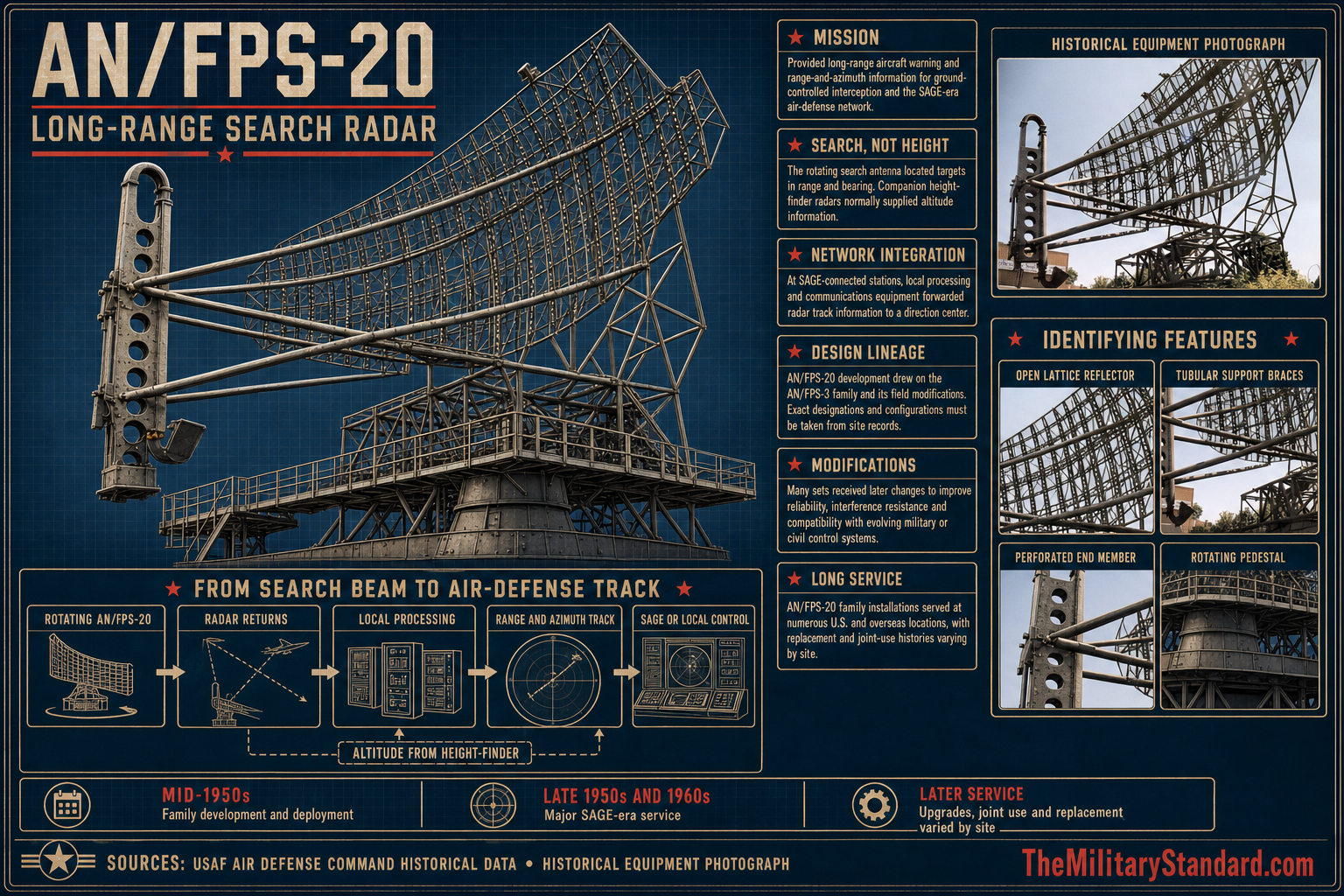
Common Name: Long-Range Search Radar
System Family: ADC Permanent Radar Network; Mobile Radar Program; SAGE; Texas Towers; FPS-20 ECCM family
Equipment Category: Fixed L-band high-power long-range air-surveillance / early-warning search radar
Primary service: United States Air Force
Primary command context: Air Defense Command, Aerospace Defense Command, NORAD, SAGE, permanent and mobile radar programs, Texas Towers, and later FAA joint-use surveillance
Principal variants and descendants: AN/FPS-20A, AN/FPS-64/64A, AN/FPS-65, AN/FPS-66/66A, AN/FPS-67/67A/67B, AN/FPS-87A, AN/FPS-91A, and site-specific AN/FPS-20Q
RF pulse width: 6 microseconds
Power-amplifier modulator video pulse width: 8 microseconds
Pulse repetition frequency: 360 pulses per second nominal
Transmitter duty cycle: 0.00216
Modulator duty cycle: 0.00288
RF source: Three-cavity high-power klystron
Receiver noise figure: 9 dB
Moving-target indication: Two quartz delay lines in cascade with feedback, plus supporting coherent and noncoherent processing
Reported historical range: More than 200 miles in the official Air Force historical summary
Altitude context: The AN/FPS-3 predecessor was described as effective to about 55,000 feet; GPA-27/FPS-20 development raised the useful capability to roughly 65,000 feet. This is a development-context figure, not a universal target-detection guarantee.
Antenna: AT-572/FPS-20 reflector with line-feed arrangement in the high-power conversion configuration
Antenna gain: Approximately 35 dB at 1300 MHz, nose of beam, in MIL-HDBK-162A
Rotation: The primary handbook performance data explicitly references 3.3 or 5.0 rpm for velocity-response shaping. Later site-specific configurations could provide additional speeds.
Electrical service: MIL-HDBK-162A prints 120/206 volts, plus or minus 5 volts, three-phase, 60 plus or minus 5 cycles, four-wire. The Oceana AN/FPS-20Q document gives 120/208 volts for that site-specific configuration.
Temperate radar control shelter: Approximately 25 feet 10 inches by 48 feet 4 inches inside dimensions, with 10 feet clear height, for one active and one standby channel
ADC classification: Long Range Search
Frequency Band: L-band
Frequency MHz: 1250-1350 MHz in MIL-HDBK-162A high-power configuration; site-specific FPS-20Q document gives 1280-1350 MHz
Peak Power: 2 MW minimum peak
Average Power: 4.32 kW minimum average RF output in MIL-HDBK-162A
Radar Manufacturer: Bendix Radio Division, Bendix Aviation Corporation
Primary Role: Long-range aircraft early warning and air-surveillance search, providing range and azimuth for GCI and SAGE air-defense control
Detection Range: More than 200 miles in official Air Force historical summary; no universal target-specific detection benchmark established in reviewed primary technical entry
Altitude Coverage: Development context improved from about 55,000 ft for FPS-3 to about 65,000 ft with GPA-27/FPS-20 lineage; not a universal target ceiling
Antenna Type & Dimensions: AT-572/FPS-20 reflector with line feed; approximately 35 dB one-way gain at 1300 MHz; exact reflector dimensions unresolved in reviewed primary technical pages
Antenna Rotation Rate: Primary handbook performance data references 3.3 or 5.0 rpm; later site-specific configurations could provide additional speeds including 6.6 and 10 rpm
Transmitter & Receiver: Three-cavity high-power klystron; 6-microsecond RF pulse; 360 pps nominal; 9-dB receiver noise figure; dual quartz-delay-line MTI with feedback; video enhancement and antichaff receiver
Power Requirements: MIL-HDBK-162A prints 120/206 VAC plus or minus 5 V, 3-phase, 60 plus or minus 5 Hz, 4-wire; Oceana FPS-20Q documentation gives 120/208 VAC
Introduced: AN/GPA-27 field modification began in 1956; integral AN/FPS-20 equipment began air-search duties in 1957
Retired: No single retirement date. Baseline military sets were converted or replaced from the 1960s onward; FAA still counted 29 AN/FPS-20 systems in 1993 and maintained solid-state/digital-MTI family documentation into the modern era
Replaced: AN/FPS-3, AN/FPS-3A and fixed AN/MPS-7 through GPA-27/GPA-57/GPA-58 conversion paths
Replaced By: AN/FPS-64/65/66/67 ECCM conversions; AN/FPS-87A and AN/FPS-91A modifications; site-specific newer search radars including FPS-24/27/35 and later FAA ARSR systems
Associated Systems: AN/GPA-27/27A; AN/GPA-57/57A; AN/GPA-58A/58B; AN/GPA-102; AN/GPA-103; AN/FPS-6 family; SAGE data systems; AN/FPS-64/65/66/67; AN/FPS-87A; AN/FPS-91A; FAA joint-use; Texas Towers
Preserved Examples: No complete original operational U.S. AN/FPS-20 set confirmed. Preserved antenna monuments are documented at Clinton, Ontario, and Kamloops, British Columbia; numerous former U.S. stations retain structural or successor-system remains.
Equipment Identity
The AN/FPS-20 became one of the defining long-range search radars of the mature 1950s continental air-defense network. Air Defense Command's own equipment summary classifies both AN/FPS-20 and AN/FPS-20A as Long Range Search. That simple label concealed a major technical transition. The FPS-20 was not merely another antenna at a radar station. It represented the conversion of the early AN/FPS-3 generation into a higher-power, more maintainable, better-clutter-rejecting system suited to the expanding Semi-Automatic Ground Environment and to a defense network expected to cope with faster aircraft, higher operating altitudes, deliberate electronic interference, and increasingly dense radar coverage.
The equipment's importance came from scale as well as performance. Headquarters Air Combat Command's historical study Searching the Skies states that more than 200 AN/FPS-20-family units were built and that the radar became a mainstay at many U.S. air-defense sites. By the end of 1958, NORAD statistical reporting showed thirty-four operational permanent-system stations using FPS-20 as prime search equipment, plus additional sets in the first and second phases of the Mobile Radar Program. That rapid spread made the system one of the principal bridges between the first postwar radar network and the automated SAGE era.
The designation also describes a family whose boundaries must be handled carefully. MIL-HDBK-162A explains that several conversion kits could transform existing AN/FPS-3, AN/FPS-3A, or fixed AN/MPS-7 installations into AN/FPS-20 or AN/FPS-20A configurations. Later ECCM packages created AN/FPS-64, FPS-65, FPS-66, and FPS-67 designations, while other receiver and antenna changes produced additional descendants. The history of one station cannot therefore be reconstructed by assuming that every radar labeled FPS-20 had an identical manufacturing history, cabinet arrangement, antenna pedestal, or later modification path.
Development Lineage from AN/FPS-3
The AN/FPS-20 grew directly from the Bendix AN/FPS-3. The FPS-3 had been one of the most important early permanent-network search radars, but the rapidly changing bomber threat exposed limitations in altitude capability, clutter rejection, maintainability, and resistance to electronic countermeasures. The Air Force did not discard the entire installed base. Instead it pursued field modifications and new production that would preserve usable towers, antennas, buildings, and infrastructure while improving the electronic core.
Searching the Skies describes the first step as the AN/GPA-27 modification. The FPS-3 could detect targets to roughly 55,000 feet in the Air Force historical summary, while the GPA-27 improvement raised the effective altitude capability to about 65,000 feet. Installation of the kits began in 1956. When the improvement was incorporated into new equipment rather than added as a field kit, the resulting high-power radar received the AN/FPS-20 designation and began air-search duties in 1957.
MIL-HDBK-162A provides the more precise conversion relationships. AN/GPA-27 converted an AN/FPS-3 into a dual-modulator AN/FPS-20. AN/GPA-57 performed the comparable conversion on an AN/FPS-3A, and AN/GPA-58B converted a fixed AN/MPS-7 installation. The suffix-A kits followed a different modulator arrangement: AN/GPA-27A, AN/GPA-57A, and AN/GPA-58A produced the single-modulator AN/FPS-20A configuration. These relationships matter because the resulting radar could be a converted earlier installation rather than a wholly new site or wholly new set.
The conversion program also changed the mechanical interface between antenna and electronics. Earlier configurations used slip rings for substantial electrical connections through the rotating assembly. The FPS-20 conversion introduced a rotary joint arrangement that allowed the major transmitters, receivers, and controls to be housed in a heated shelter away from the rotating antenna. This made the equipment easier to maintain and protected sensitive electronics from the harsher environment of the antenna structure.
High-Power Configuration and Dual-Channel Concept
The high-power FPS-20 configuration documented in MIL-HDBK-162A used a three-cavity klystron and specified at least two megawatts of peak output. This is a critical source distinction. Popular summaries sometimes repeat older AN/FPS-3 magnetron figures when describing the FPS-20. The primary handbook for the high-power conversion configuration instead gives 2 MW minimum peak power and 4,320 watts minimum average RF output. Those figures are used in the equipment master because they are directly tied to the AN/FPS-20 conversion description.
The dual-channel arrangement was operationally valuable. The radar control shelter could contain one active channel and one standby channel. A standby transmitter or receiver could be serviced, tested, or used for training while the operational channel continued the surveillance mission. This reduced the maintenance penalty of taking a major search radar completely off line and gave technicians a safer, more controlled environment than working directly in a rotating antenna structure.
The FPS-20A did not simply mean "a better FPS-20" in a generic sense. The military handbook distinguishes the baseline FPS-20 as a dual-modulator system and FPS-20A as a single-modulator configuration created through the corresponding A-suffix conversion kits. Later station records may use the two designations sequentially as equipment was modified, but the suffix should be preserved rather than treated as a decorative label.
Purpose and Operational Role
The radar's mission was long-range two-dimensional surveillance. It measured range and azimuth of aircraft and supplied those tracks to the air-defense control system. It did not by itself provide the precise altitude information normally obtained from a dedicated height finder such as AN/FPS-6 or its successors. A typical ADC station therefore paired the FPS-20 search radar with one or more height-finding sets so that controllers could build a three-dimensional understanding of a target's position.
That search function supported several missions at once. The radar provided early warning against unidentified aircraft approaching defended regions. It furnished ground-controlled-intercept information for fighter direction. It supplied the surveillance picture required for identification and track correlation. In SAGE-connected areas, its data became one input to computer-assisted direction centers that combined reports from many radars and other sensors into a broader regional picture.
The radar's value was especially high because it arrived while the national network was expanding and automating. Early permanent-system sites had been constructed around first-generation equipment and manual plotting procedures. By the late 1950s, the United States was installing faster computers, digital data links, new height finders, gap fillers, frequency-diversity radars, and offshore sensors. The FPS-20 gave many existing stations a long-range search capability that could be inserted into that changing system without rebuilding every site from the ground up.
Technical Specifications and Performance
The primary high-power technical entry places the FPS-20 between 1250 and 1350 MHz in the L-band. The transmitter produced at least 2 MW peak and 4.32 kW average RF output, with a six-microsecond RF pulse and a nominal 360-pulse-per-second repetition rate. The 4.32-kW average figure is internally consistent with the specified 0.00216 transmitter duty cycle and is an official minimum in the handbook rather than a derived estimate.
The receiver noise figure is given as 9 dB. The system's moving-target-indicator performance relied on two quartz delay lines in cascade with feedback. MIL-HDBK-162A gives cancellation figures exceeding 40 dB for a single line and 50 dB for cascaded operation, while also listing practical limitations from the coherent oscillator, stable local oscillator, receiver cabinet, and transmitter. These numbers illustrate an important point: clutter rejection was a chain performance problem. A very good delay line alone could not produce equally good operational cancellation if oscillator stability, transmitter behavior, or receiver noise became the limiting factor.
The official Air Force historical study describes the radar's range as more than 200 miles. That is useful as a broad historical performance statement, but the reviewed primary handbook entry does not supply a single target-specific benchmark such as "fighter at X altitude at Y miles." The equipment master therefore keeps "over 200 miles" as an official historical summary and does not convert it into an exact universal detection range for every target and every site.
Altitude is handled with the same caution. Searching the Skies uses the FPS-3 to GPA-27 development story to describe a rise from roughly 55,000 to 65,000 feet. That figure explains why the modification mattered, but it is not treated as a fixed radar ceiling. Radar detection altitude depends on range, target size, antenna pattern, terrain, atmospheric conditions, and signal-processing performance. The page therefore uses the 65,000-foot figure as development context rather than as an absolute maximum.
How the Radar Worked
The basic search cycle was straightforward. The rotating L-band antenna transmitted a high-power pulse, then the receiver listened for reflected energy. The elapsed time between pulse transmission and echo return yielded range. The azimuth of the antenna when the echo was received yielded bearing. Repeating that process hundreds of times per second while the antenna rotated created a circular surveillance picture around the station.
High peak power mattered because radar echoes are extraordinarily weak by the time they return from distant targets. The two-megawatt pulse was not transmitted continuously. It lasted only a few microseconds, allowing the radar to combine high instantaneous power with a much lower average RF output. This pulsed architecture gave the receiver time to listen between transmissions and measure the delay that encoded target range.
The line-feed antenna arrangement replaced the older four-horn feed used in related earlier configurations. The exact reflector dimensions were not established in the reviewed primary technical pages, so the equipment master records the AT-572/FPS-20 reflector and approximate antenna gain rather than estimating size from photographs. MIL-HDBK-162A gives about 35 dB one-way gain at 1300 MHz at the nose of the beam.
Moving-Target Indication and Clutter Rejection
Ground clutter was one of the defining problems of air-surveillance radar. Hills, buildings, trees, coastlines, and other fixed objects could return more energy than an aircraft. The FPS-20 used moving-target-indication circuits to suppress returns whose phase behavior indicated stationary objects and to emphasize moving targets. The quartz delay-line system compared successive pulses so that repeated fixed echoes canceled more strongly than echoes from moving aircraft.
The system also improved power-supply regulation because ripple and instability could degrade MTI cancellation. This is a good example of how radar performance depended on apparently mundane electronics. Better clutter rejection was not produced only by a new antenna or more transmitter power. Oscillators, power supplies, receivers, delay lines, and timing circuits all had to remain stable enough for coherent comparisons to work.
MIL-HDBK-162A (link to this PDF is in the Sources & References section at the bottom of this page) also describes a video-enhancement circuit designed to reduce interference from other radars operating at different pulse-repetition frequencies. That feature became increasingly important as the continental network grew denser. A station no longer operated in an empty electromagnetic environment. Nearby surveillance radars, height finders, military systems, and later civil radars could produce asynchronous interference that complicated the display.
The handbook also identifies an antichaff receiver. Chaff was a deliberate countermeasure consisting of clouds of reflective material intended to produce confusing radar returns. The presence of antichaff processing shows that the FPS-20 was designed not merely for peaceful traffic observation but for wartime surveillance against an opponent expected to use electronic and physical countermeasures.
Typical Installation and Physical Layout
A temperate FPS-20 installation used a radar control shelter with inside dimensions of approximately 25 feet 10 inches by 48 feet 4 inches and a clear height of about 10 feet. The shelter held the active and standby channels, controls, receiver and transmitter equipment, and associated electronics. Moving this equipment into a controlled building reduced weather exposure and gave technicians room to maintain the system without standing inside the moving antenna assembly.
At Arctic installations, the handbook describes using the first floor of the AN/199/FPS-3 or AB-199A/FPS-3 antenna tower as the radar-control shelter. That arrangement reflects the conversion lineage. The Air Force could reuse substantial structures from the FPS-3 generation while replacing electronic groups, feeds, pedestal interfaces, and control systems.
The antenna conversion also depended on the starting equipment. MIL-HDBK-162A lists conversion arrangements for AN/FPS-3, AN/FPS-3A, and AN/MPS-7 pedestals. The resulting equipment included the AT-572/FPS-20 reflector, TG-36/GPS antenna drive, and pedestal-conversion kits that created FPS-20-compatible assemblies. This is why a station photograph alone cannot always reveal whether a particular FPS-20 was a new installation or a converted predecessor.
Power requirements were significant, but the reviewed handbook pages do not give a single whole-site kilowatt requirement comparable to the transmitter RF output. They do give the incoming service as three-phase, 60 plus or minus 5 cycles, four-wire, and print the voltage as 120/206 plus or minus 5 volts. Because that value is unusual, it is preserved exactly as printed rather than silently normalized to the more familiar 120/208-volt service.
SAGE Integration
The FPS-20 came into service just as SAGE was transforming air-defense command and control. SAGE did not make the radar itself three-dimensional or automatically identify every target. Instead, it created a system in which radar reports from many stations could be digitized, transmitted, correlated, displayed, and used by controllers at direction centers. Search radar tracks, height information, identification data, flight plans, interceptor status, and weapons information could be combined more rapidly than in the earlier manual network.
At many sites, FPS-20-family radar became one of the principal surveillance inputs to SAGE. The radar detected targets locally, while associated data-processing and communication equipment carried track information onward. Direction-center personnel and computers then integrated the information with returns from neighboring stations and other sensors. The strategic value of the FPS-20 therefore lay as much in connectivity as in transmitter power.
This relationship also changed maintenance priorities. A radar could be producing a strong local display and still be operationally deficient if its data link, identification equipment, height-finder coordination, or SAGE interface failed. Conversely, a reliable standby channel and well-maintained communications path could keep a site contributing to the network even while technicians repaired part of the local radar system.
Rapid Deployment in the Permanent Network
The FPS-20 spread quickly. A declassified NORAD/CONAD statistical summary for 31 December 1958 counted seventy-four operational permanent P-sites. Their prime search equipment included twenty-five CPS-6B/FPS-10 systems, fifteen MPS-7/FPS-3 systems, and thirty-four FPS-20s. The same summary counted eight FPS-20s among twenty-nine operational first-phase mobile sites and five among thirteen operational second-phase mobile sites. In that snapshot alone, forty-seven operational land-based sites were using FPS-20 as their prime search radar.
That statistic shows how quickly the system moved from modernization concept to network mainstay. Only a few years earlier the FPS-3 generation had dominated much of the permanent network. By late 1958 the FPS-20 had become the largest single prime-search category in the permanent-site table. The transition also demonstrates the value of conversion engineering. The Air Force could modernize existing radar locations faster than it could build an entirely new national network.
Station histories show that FPS-20 and FPS-20A service was geographically widespread. Installations appeared along the Atlantic and Pacific coasts, across the northern tier, in the central states, in the Southwest, and at southern defense locations. The equipment also appeared at mobile-program stations that later became permanent Air Force Stations. The family was not tied to one coast or one specific sector.
Mobile Radar Program Use
The name "Mobile Radar Program" can be misleading when read from a later perspective. Many program sites evolved into fixed installations, and equipment described as mobile could remain at a location for years. The FPS-20 family entered this program as the Air Force upgraded stations from earlier MPS-7, FPS-3, FPS-8, and related equipment to more capable long-range search radar.
ADC tables document representative FPS-20 or FPS-20A use at Amarillo, Texas; Texarkana, Arkansas; West Mesa and Las Cruces, New Mexico; Almaden, California; Ellsworth AFB, South Dakota; Miles City and nearby Montana sites; Gettysburg, South Dakota; Hunter AFB, Georgia; Charleston AFB, South Carolina; England AFB, Louisiana; and Houma NAS, Louisiana. These examples demonstrate that the radar family was part of the national expansion and modernization program, not merely a replacement restricted to the earliest P-sites.
The mobility of the program did not imply that a two-megawatt radar could be casually moved like a truck-mounted tactical set. The system still required substantial antenna, shelter, power, communications, and maintenance infrastructure. "Mobile" referred more to the program origin and deployable heritage than to frequent operational relocation of a fully installed radar.
Texas Towers
The FPS-20 family also served offshore on the Texas Towers. These fixed platforms were built far out in the Atlantic to extend radar coverage seaward toward likely bomber approach routes. Their search radars operated alongside FPS-6-series height finders and transmitted surveillance information back into the northeastern air-defense system.
ADC records show AN/FPS-20 and AN/FPS-20A service on the completed offshore towers. Texas Tower No. 3 at Nantucket Shoal used FPS-20 beginning in 1958, later FPS-20A, and then FPS-67 as the family was modernized. Texas Tower No. 4 on Unnamed Shoal entered documented radar operation in April 1959 with FPS-20-family search equipment and two FPS-6A height finders, then operated as a SAGE unit before the platform collapsed on 15 January 1961.
The loss of Texas Tower No. 4 killed fourteen Air Force personnel and fourteen civilian repairmen. The radar did not cause the structural failure, but the event became the most tragic operational episode associated with a site carrying FPS-20-family equipment. It also illustrates the extreme environments in which the Air Force expected the continental surveillance network to function. A radar that was comparatively accessible in a normal ground shelter became far harder to maintain when mounted on a storm-battered offshore platform.
Electronic Counter-Countermeasures Modernization
The FPS-20 family became a foundation for later electronic-counter-countermeasures upgrades. By the end of the 1950s, the Soviet threat was no longer understood as a simple problem of detecting an unprotected bomber. Air-defense radars had to remain useful in the presence of jamming, chaff, mutual interference, and deliberate attempts to saturate or confuse surveillance systems.
Bendix received a June 1959 contract for the modification programs later associated with AN/GPA-102 and AN/GPA-103. A declassified NORAD study records an initial Bendix contract for forty-four FPS-20 modification kits and describes testing beginning in 1960, followed by correction of deficiencies and a formal Air Force implementation plan in September 1961.
The two principal kits were closely related but not identical. The NORAD study states that GPA-102 and GPA-103 were essentially identical except that the GPA-103 package used a velocity filter where the GPA-102 package used PISAB processing. The package set included diplexing, coherent and noncoherent MTI, Dicke-Fix processing, log/logic functions, side-lobe cancellation, clutter gating, video integration, anti-jam controls, and cross-gating features.
ADC's equipment summary gives the resulting designation map. AN/FPS-20 with AN/GPA-102 became AN/FPS-64 or FPS-64A. AN/FPS-20 with AN/GPA-103 became AN/FPS-65. AN/FPS-20A with AN/GPA-102 became AN/FPS-66 or FPS-66A. AN/FPS-20A with AN/GPA-103 became AN/FPS-67, FPS-67A, or FPS-67B. Those mappings are retained exactly because they allow site histories to explain designation changes that would otherwise look like entirely new radar installations.
Further modifications extended the family. ADC identifies AN/FPS-87A as an FPS-20A with OA-4381 receiver-group modification and AN/FPS-91A as an FPS-20A with OA-3424. The OA-3424 is described as a high-gain antenna providing more effective ECCM capability. AN/FPS-93A then combined the AN/FPS-87A arrangement with OA-3424. These designations show how one basic radar lineage could remain useful through layered receiver, antenna, and signal-processing upgrades.
FPS-20B and Other Variant Caution
The official Air Force historical narrative refers to FPS-20B in the broader family story, but the reviewed primary technical material did not provide a definitive engineering table describing every difference between FPS-20A and FPS-20B. Specialist radar histories associate FPS-20B with additional antenna and component changes, but those details are not promoted to master specification fields without stronger primary support.
The same caution applies to later FAA and site-specific forms. An installation may be described colloquially as "FPS-20" even after extensive receiver, MTI, antenna, or automation modifications. Equipment histories must therefore preserve the designation and date documented at the site instead of assuming that a radar photographed in 1985 still had the exact electronics described in a 1965 military handbook.
AN/FPS-20Q at Naval Air Station Oceana
A surviving Bendix engineering description for the AN/FPS-20Q at Naval Air Station Oceana provides an unusually detailed example of a later site-specific configuration. It describes the radar as a high-powered dual-channel long-range system using a common antenna, based on FPS-20A but incorporating an OA-4527/FPS-87 Canadian Arsenal Dicke-Fix receiver and an AN/FPS-37 antenna with a circular/linear polarizer.
The Oceana system was housed in an Arctic-type tower approximately seventy-five feet above ground and protected by a fifty-five-foot geodesic radome. Its document gives a single cosecant-squared beam, about 36 dB horizontal antenna gain, a horizontal beamwidth of 1.3 degrees, vertical beamwidth of about 60 degrees, and selectable rotation speeds of 3.3, 5, 6.6, and 10 rpm. It lists horizontal or circular polarization, an L-3035 liquid-cooled klystron, 1280 to 1350 MHz frequency, and about 350 pulses per second.
Those figures are not used as universal baseline FPS-20 specifications. They demonstrate how far the family could evolve at a specific site. The Oceana document also gives 120/208-volt, three-phase, 60-cycle primary power, while MIL-HDBK-162A prints 120/206 volts for the earlier high-power conversion description. Both values are retained as source-specific evidence rather than silently forcing one document to match the other.
FAA and Joint-Use Service
The FPS-20 family outlived the period when Air Defense Command was its only important user. Many military radar sites became joint-use facilities or were transferred to the Federal Aviation Administration, where long-range surveillance supported both civil air-traffic control and national defense. The radar's rugged infrastructure and repeated electronic upgrades made it economical to keep useful installations operating rather than replace every site immediately.
A 1993 FAA report counted twenty-nine AN/FPS-20 systems among the agency's National Airspace System primary long-range radars, alongside forty-seven ARSR-1 and ARSR-2 systems. That is extraordinary longevity for a family whose first operational service began in the 1950s. The number does not mean those radars retained original 1957 electronics. By then many had received solid-state receivers, digital moving-target-indicator equipment, new processors, and other modifications.
FAA Order JO 6340.22, originally issued in 1989, specifically covered maintenance of the AN/FPS-20 family with solid-state receiver and digital moving-target indicator. Its long administrative life, with cancellation only in 2021, provides documentary evidence of how deeply the FPS-20 lineage penetrated later civil-military surveillance infrastructure. A separate FAA radiation-safety order also continued to list the FPS-20 series among major radar types requiring controlled maintenance procedures.
The family eventually yielded to modern Air Route Surveillance Radar systems, especially ARSR-4 in joint-use locations. FAA planning documents explicitly treated the newer radar as replacement for older ARSR-1/2/3 and AN/FPS-20/60-series systems. The successor therefore was not a single Cold War military radar but a later national air-surveillance architecture combining FAA and defense requirements.
Known U.S. Military Locations Using AN/FPS-20 Family Equipment
The following examples are representative rather than an exhaustive lifetime inventory. ADC tables document FPS-20 or FPS-20A at permanent, mobile-program, offshore, and other radar installations across the country.
- Calumet Air Force Station, Michigan, P-16, operated FPS-20-family search radar before later modernization to FPS-64 and other equipment.
- Wadena Air Force Station, Minnesota, P-17, used FPS-20 before conversion to FPS-64-family ECCM equipment.
- Chandler Air Force Station, Minnesota, P-18, operated FPS-20 before later FPS-64 modernization.
- Antigo Air Force Station, Wisconsin, P-19, used FPS-20 and later FPS-20A before subsequent frequency-diversity search equipment.
- Selfridge Air Force Base radar site, Michigan, P-20, carried FPS-20 in the ADC equipment sequence.
- Condon Air Force Station, Oregon, P-32, used FPS-20 and later FPS-20A.
- Montauk Air Force Station, New York, P-45, operated FPS-20 during the late 1950s and early 1960s before later modernization.
- Blaine Air Force Station, Washington, P-46, used FPS-20A during modernization of the permanent network.
- Hutchinson Air Force Station, Kansas, P-47, operated FPS-20 and later FPS-20A before conversion to FPS-66-family equipment.
- Moriarty Air Force Station, New Mexico, P-51, used FPS-20 during its late-1950s operational period.
- Naselle Air Force Station, Washington, P-57, used FPS-20A before later FPS-67-family modernization.
- Mather Air Force Base radar site, California, P-58, operated FPS-20A in the early 1960s.
- Boron Air Force Station, California, P-59, used FPS-20A before later search-radar modernization.
- Colville Air Force Station, Washington, P-60, used FPS-20 and FPS-20A during the final years of its operation.
- Blue Knob Park Air Force Station, Pennsylvania, P-63, operated FPS-20A during its short permanent-network phase.
- Charleston Air Force Station, Maine, P-65, used FPS-20A and later FPS-20 in the station equipment sequence alongside newer systems.
- Sault Ste. Marie Air Force Station, Michigan, P-66, used FPS-20 and later FPS-20A before subsequent modernization.
- Custer Air Force Station, Michigan, P-67, operated FPS-20 and FPS-20A.
- Finland Air Force Station, Minnesota, P-69, used FPS-20 before later FPS-64-family conversion.
- Omaha Air Force Station, Nebraska, P-71, operated FPS-20 and FPS-20A.
- Olathe Air Force Station, Kansas, P-72, used FPS-20 and later FPS-20A.
- Amarillo Air Force Station, Texas, M-88, operated FPS-20A within the Mobile Radar Program.
- Texarkana Air Force Station, Arkansas, M-91, used FPS-20 and FPS-20A during successive years.
- West Mesa Air Force Station, New Mexico, M-94, operated FPS-20A.
- Las Cruces Air Force Station, New Mexico, M-95, used FPS-20 and later FPS-20A.
- Almaden Air Force Station, California, M-96, operated FPS-20 during the late 1950s and early 1960s.
- Ellsworth Air Force Base radar site, South Dakota, M-97, used FPS-20A.
- Miles City Air Force Station, Montana, M-98, used FPS-20 and FPS-20A before later FPS-66-family equipment.
- Gettysburg Air Force Station, South Dakota, M-99, used FPS-20 before later FPS-66-family modernization.
- Hunter Air Force Base radar site, Georgia, M-112, operated FPS-20A before later FPS-67-family equipment.
- Charleston Air Force Base radar site, South Carolina, M-113, operated FPS-20A before later FPS-66-family modernization.
- England Air Force Base radar site, Louisiana, M-125, used FPS-20 and FPS-20A.
- Houma Naval Air Station radar site, Louisiana, M-126, used FPS-20 and FPS-20A before later FPS-67-family modernization.
- Texas Tower No. 3, Nantucket Shoal, operated FPS-20 beginning in 1958, later FPS-20A, and then FPS-67.
- Texas Tower No. 4, Unnamed Shoal, operated FPS-20-family search radar from 1959 and FPS-20A in the period before its 1961 collapse.
This broad geographic distribution is the strongest evidence of the system's centrality. The FPS-20 was not an experimental set confined to one sector. It became a standard long-range search solution throughout the continental network and served as the base hardware for several subsequent ECCM configurations.
Operational Events and Conflict Context
No evidence located shows an FPS-20 detecting an actual Soviet bomber attack on the United States, because the continental air-defense network never faced the strategic bombing assault it was built to resist. The radar's operational history was instead one of continuous alert, exercises, identification problems, maintenance, false alarms, civil-aircraft tracking, and integration with interceptor and missile-defense systems during the Cold War.
Its most dramatic site event was the Texas Tower No. 4 disaster. The collapse was a structural failure of the offshore platform during a storm, not a failure of the radar system. Even so, the loss destroyed an operating FPS-20-family surveillance site and killed military radar personnel as well as civilian workers. It exposed the human and engineering cost of pushing radar coverage far offshore in pursuit of earlier warning.
The radar family also participated indirectly in every major Cold War air-defense alert because it formed part of the national warning network. During periods such as the Cuban Missile Crisis, ADC and NORAD stations maintained heightened readiness, but a site-specific event log tying particular FPS-20 serial numbers to a unique crisis action was not located.
Replacement and Retirement
Replacement occurred through two overlapping paths. One path was internal modernization. FPS-20 and FPS-20A sets became FPS-64, FPS-65, FPS-66, FPS-67, FPS-87A, FPS-91A, and other descendants as ECCM, receiver, and antenna packages were installed. A station could therefore retire the designation "FPS-20" while continuing to use much of the same underlying radar lineage.
The second path was replacement by newer search-radar architectures. High-power frequency-diversity systems such as FPS-24, FPS-27, and FPS-35 entered service at selected stations. Other sites later used FAA ARSR equipment, FPS-66-family systems, or entirely different surveillance radars. Because each station modernized on a different schedule, there was no single national day when the FPS-20 disappeared from service.
The FAA era extended the practical life of the family far beyond its original military generation. Solid-state receiver and digital-MTI modifications allowed tube-era infrastructure to remain useful in the National Airspace System. By 1993 the FAA still counted twenty-nine FPS-20 systems. The family therefore moved from a 1950s continental-defense mainstay to a long-lived joint civil-military surveillance platform.
Preservation and Surviving Evidence
No complete original operational AN/FPS-20 system in the United States was confirmed. Many former radar sites retain towers, foundations, operations buildings, radomes, or later successor antennas, but those surviving structures should not automatically be labeled preserved FPS-20 hardware. The radar family underwent too many conversions and site replacements for that assumption to be safe.
Canada preserves clearer antenna monuments. Veterans Affairs Canada documents the No. 1 Radar and Communications School memorial at Clinton, Ontario, which incorporates an FPS-20 search-radar antenna donated after the station closed. Pinetree Line historical material also documents a former FPS-20 antenna preserved in Kamloops, British Columbia. These are important surviving artifacts even though they are outside the United States.
Photographic evidence is extensive. The official ADC historical volume includes an AN/FPS-20 photograph. Searching the Skies supplies another widely reproduced Air Force image. Radomes.org preserves period photographs from sites and the Bendix Verona test facility, along with images of klystron components and an FPS-20 tower floor plan. The Oceana AN/FPS-20Q engineering description preserves a detailed later configuration.
Chronology
- Late 1940s to early 1950s Bendix AN/FPS-3 became a principal early permanent-network L-band search radar and created the installed base from which much of the FPS-20 conversion lineage developed.
- 1955 Air-defense planning increasingly emphasized higher-altitude coverage, improved clutter rejection, SAGE integration, and resistance to electronic countermeasures.
- 1956 Installation of AN/GPA-27 improvement kits on AN/FPS-3 equipment began according to the official Air Force historical summary.
- 1956 GPA-27 development raised the historical altitude-capability context from roughly 55,000 feet for FPS-3 to roughly 65,000 feet.
- 1957 New radar sets incorporating the improvements received the AN/FPS-20 designation and began air-search duties.
- 1958-10 Texas Tower No. 3 began documented FPS-20 search-radar operation at Nantucket Shoal.
- 1958-12-31 NORAD counted thirty-four FPS-20s as prime search equipment at seventy-four permanent P-sites.
- 1958-12-31 NORAD also counted eight FPS-20s at first-phase Mobile Radar Program sites and five at second-phase mobile sites.
- 1959-04 Texas Tower No. 4 entered documented FPS-20-family operation at Unnamed Shoal.
- 1959-06 Bendix received the Air Force contract associated with the MK-447 / AN/GPA-103 and MK-448 / AN/GPA-102 ECCM modification programs.
- 1959 FPS-20 and FPS-20A deployment continued to expand through permanent and mobile-program radar sites.
- 1960 Texas Towers No. 3 and No. 4 were operating FPS-20A configurations in the ADC equipment sequence.
- 1960 Initial testing began on the FPS-20 ECCM modification program described in later NORAD documentation.
- 1961-01-15 Texas Tower No. 4 collapsed during a winter storm, killing fourteen Air Force personnel and fourteen civilian workers and destroying its operating radar site.
- 1961-09 The Air Force approved the implementation plan for the FPS-20 GPA-102/GPA-103 ECCM modernization after test deficiencies were addressed.
- 1961-12 The national SAGE system reached broad operational completion, increasing the importance of network-compatible long-range radar inputs.
- 1962 ADC station tables increasingly show FPS-64, FPS-65, FPS-66, and FPS-67 designations as FPS-20-family ECCM conversions entered the network.
- 1962 ADC documented the mapping of GPA-102 and GPA-103 modifications into the FPS-64/65/66/67 family.
- 1963-01-15 Texas Tower No. 2 ended service after progressing through FPS-20-family modernization to FPS-67.
- 1963-03-25 Texas Tower No. 3 ended service after progressing from FPS-20 through FPS-20A to FPS-67.
- 1963 The fixed Texas Tower radar program ended, removing one of the most unusual operating environments used by the FPS-20 family.
- 1964 Later military and FAA modernization continued as individual sites retained, converted, or replaced FPS-20-family equipment.
- 1965-12-15 MIL-HDBK-162A published detailed FPS-20 conversion, transmitter, receiver, MTI, antenna, power, and shelter specifications.
- Late 1960s FPS-20-family descendants remained widespread while newer frequency-diversity and FAA joint-use systems replaced baseline equipment at selected stations.
- 1970s Military-only FPS-20 designations declined, but converted family hardware and FAA-operated descendants continued in service.
- 1980s FAA joint-use sites continued operating extensively modified FPS-20-family radars.
- 1989 FAA maintenance Order 6340.22 formally covered AN/FPS-20-family radars equipped with solid-state receiver and digital moving-target indicator.
- 1993 An FAA surveillance-system report counted twenty-nine AN/FPS-20 systems still operating in the National Airspace System.
- 1997-06 Headquarters Air Combat Command published Searching the Skies, describing the FPS-20 as a Bendix-built long-range radar, stating that more than 200 units were built, and documenting its modernization lineage.
- 2000s FAA radiation and maintenance documentation continued to list FPS-20-series equipment while ARSR-4 replacement advanced.
- 2021 FAA maintenance Order JO 6340.22 for the FPS-20 family with solid-state receiver and digital MTI was cancelled, marking the administrative end of a very long maintenance lineage.
- Present No complete original U.S. AN/FPS-20 system has been confirmed in the reviewed public record, while photographs, manuals, converted-site remains, and preserved Canadian antenna monuments document the family's history.
Information sources (13)
- PDFMIL-HDBK-162A / TM 11-487C-1, Military Standardization Handbook, United States Radar Equipment, Volume 1
Primary technical source for the FPS-20 conversion architecture, 2-MW klystron transmitter, 4.32-kW minimum average output, 1250-1350 MHz frequency, 360-pps PRF, pulse characteristics, MTI system, antenna gain, power service, control shelter, and AN/FPS-20 versus AN/FPS-20A modulator distinction.
- PDFAerospace Defense Command, Historical Data of the Aerospace Defense Command, 1946-1973
Primary ADC source for classification of FPS-20 and FPS-20A as Long Range Search, station-level equipment sequences, Mobile Radar Program and permanent-network deployment, Texas Tower equipment, and mapping of FPS-64/65/66/67 and later ECCM variants.
- WEBDavid F. Winkler, Searching the Skies: The Legacy of the United States Cold War Defense Radar Program, Headquarters Air Combat Command
Official Air Force historical source for Bendix manufacture, 1250-1350 MHz band, over-200-mile historical range, GPA-27 development, 1957 operational introduction, more-than-200-unit production statement, and later FPS-20-family modernization.
- PDFNORAD/CONAD Historical Summary, July-December 1958
Official declassified command source for the 31 December 1958 prime-search inventory showing thirty-four FPS-20 permanent sites, eight first-phase mobile sites, and five second-phase mobile sites.
- PDFNORAD, Electronic Counter-Countermeasures in NORAD, 1963
Declassified command study used for the initial forty-four-kit FPS-20 modification contract, test and implementation chronology, GPA-102/GPA-103 package content, and the velocity-filter versus PISAB distinction.
- PDFBendix engineering description, AN/FPS-20Q Radar, Naval Air Station Oceana
Site-specific engineering source for the Oceana FPS-20Q configuration, including Arctic tower, fifty-five-foot radome, FPS-37 antenna, OA-4527/FPS-87 receiver, rotation speeds, polarization, frequency, PRF, klystron, antenna gain, and 120/208-volt power.
- PDFFederal Aviation Administration, 1993 radar-system report
Official FAA source for the late service life of the family, including the count of twenty-nine AN/FPS-20 primary long-range systems still in the National Airspace System.
- WEBFederal Aviation Administration, Order JO 6340.22
Official maintenance source documenting AN/FPS-20-family radars equipped with solid-state receiver and digital moving-target indicator and demonstrating the family's extensive post-Air Force modernization.
- PDFFederal Aviation Administration, Order 6340.28
Official FAA radiation-safety source listing FPS-20-series long-range radar equipment among systems requiring maintenance radiation-control procedures.
- WEBOnline Air Defense Radar Museum, AN/FPS-20
Specialist photographic and cross-check source for AN/FPS-20 hardware, Bendix Verona test-site photographs, klystron components, and installation imagery.
- WEBOnline Air Defense Radar Museum, FPS-3 modification tree
Specialist source used to visualize the broad FPS-3/FPS-20 modification family and later FAA-related conversions. Variant claims are not allowed to override the military handbook or ADC mapping.
- WEBVeterans Affairs Canada, No. 1 Radar and Communications School Memorial
Official Canadian memorial source confirming preservation of an FPS-20 radar antenna at Clinton, Ontario.
- WEBPinetree Line archive, AN/FPS-20
Specialist photographic and preservation source for Canadian FPS-20 installations, components, and surviving antenna monuments.