
How Air-Defense Radar Stations Worked
A Cold War air-defense radar station was more than the large antenna visible in a photograph. It was an integrated installation that detected aircraft, measured their position and altitude, checked identification responses, assembled tracks, and sent information to the people and systems directing a response. Its radar sets depended on operators, data-processing equipment, communications circuits, electrical power, cooling, maintenance shops, and sometimes an entire military support community.
This guide explains those functions and how they fit together at a typical United States Air Defense Command station. Equipment and layouts varied by site and date. Use the radar equipment index for individual systems and the radar history overview for the wider development of the defense network.
From detection to response
The basic information chain was detection, location, identification, altitude measurement, track formation, transmission, evaluation, and continued surveillance. These were functions, not necessarily eight separate machines. A later three-dimensional radar could supply measurements that an earlier station obtained from a search radar and a dedicated height finder. Likewise, identification and tracking relied on procedures and controllers as well as electronics.
- A search radar detected a return and established range and azimuth.
- Identification equipment sought a coded reply from a cooperating aircraft.
- A height finder measured altitude when the search radar could not provide it adequately.
- Operators or local processors combined observations into reports and tracks.
- Communications circuits carried the information to a direction or command center.
- Controllers evaluated the track, directed a response if needed, and kept receiving updates.
The Aerospace Defense Command historical data volume classified equipment by these different jobs, including search, height finding, combined search and height finding, gap filling, and specialized surveillance. Not every system in an equipment inventory was itself a radar sensor.
Search radar: range and bearing
The primary search radar repeatedly scanned a broad area of sky. The elapsed time between transmission and an echo gave the target's range; antenna direction gave its azimuth, or compass bearing. A conventional two-dimensional search radar therefore located a target horizontally but did not necessarily provide the altitude needed for interception. Operators saw returns on displays such as the Plan Position Indicator, or PPI, which arranged targets by direction and distance around the station.
Search equipment changed greatly over time. Early sets included SCR-270, SCR-271, AN/CPS-1, and AN/FPS-3. Later long-range examples included AN/FPS-20 and AN/FPS-35. Some search sets also supplied limited height-zone information, so "search radar" should not be taken to mean that every model produced identical data. Its equipment history and site configuration matter.
Height finders and the two-height-finder station
A conventional height finder concentrated on an aircraft already detected by search radar. Directed toward the target's bearing, it scanned in elevation to determine height. The AN/FPS-6 and AN/FPS-90 are familiar long-range examples; AN/CPS-4, AN/TPS-10, AN/FPS-4, and AN/FPS-26 belong to other height-finder families. AN/FPS-27, sometimes mistakenly placed in such lists, was a long-range search radar, not a dedicated height finder.
One search radar could detect many aircraft during a sweep, while a mechanically steered height finder generally had to spend time on selected targets. At some mature stations, a second height finder increased measurement capacity, supported repeated checks, and provided redundancy. This was a common configuration, not a rule that every station had two. Photographs and equipment tables must be dated before a particular site's antennas are interpreted.
Combined search and height information
Some systems brought search and height-finding functions into one radar. AN/CPS-6 and AN/FPS-10 were combined search-and-height examples in the earlier network. Much later, three-dimensional surveillance systems used different antenna and processing methods to report range, azimuth, and height without a separate nodding height finder beside the main search radar. The FAA and Air Force specified ARSR-4 for joint surveillance sites as a three-dimensional replacement for aging long-range radars. These examples illustrate the changing function, not a claim that the systems shared one design lineage.
Gap fillers: watching below the horizon
A long-range radar could see a high aircraft far away yet miss a low aircraft hidden by a ridge, a valley, or the curvature of the earth. Remote gap-filler radars were placed where they could cover such blind areas. AN/FPS-14 and AN/FPS-18 were short-range search radars used for that mission. Their reports fed the larger air-defense network, usually through a parent radar station.
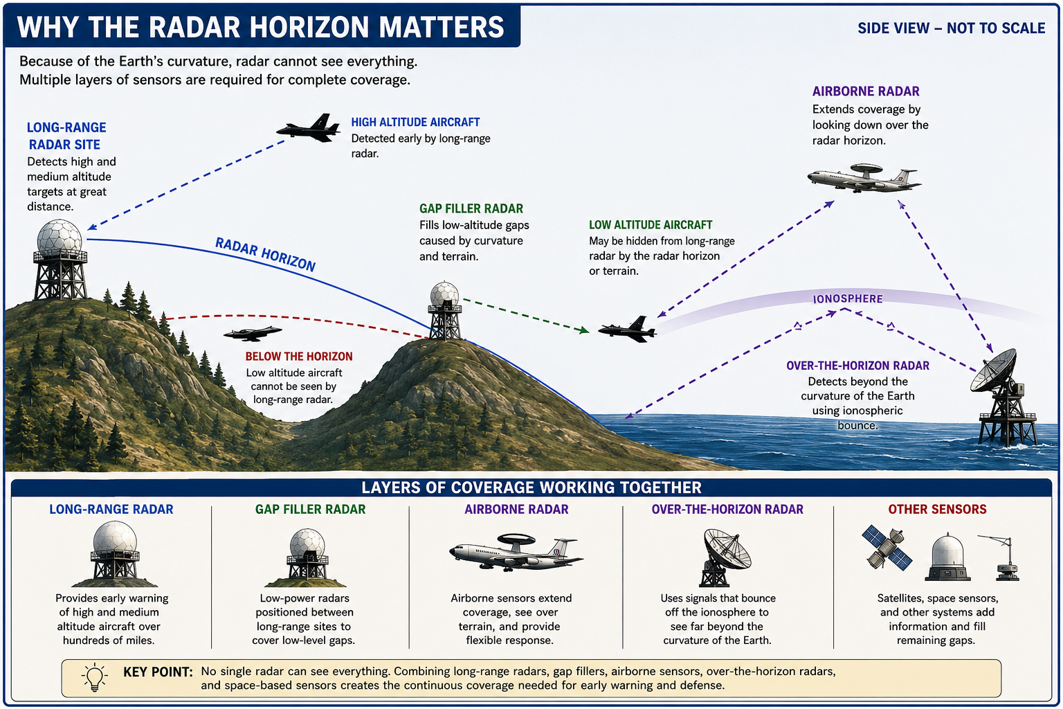
A typical annex could have one radar, a tower or support structure, a small equipment building, power and fuel equipment, fencing, an access road, and a data or telephone connection. It usually did not have its own full barracks, headquarters, medical, and recreation complex. Many were designed for unattended or limited-attendance operation. A gap filler was therefore a specialized detached sensor location, not automatically a miniature independent Air Force Station.
IFF and SIF: a reply is not a verdict
Primary radar detects an object from its reflected signal whether or not that object cooperates. Identification Friend or Foe, or IFF, interrogates an aircraft transponder and receives a coded reply when the aircraft is equipped and configured to respond. Selective Identification Feature, or SIF, expanded the usefulness of coded identification. A smaller antenna mounted on or near a search-radar antenna may belong to this equipment rather than being another search radar.
A valid reply was evidence for the identification process, not automatic proof that every aircraft was friendly. Controllers also considered codes, procedures, expected traffic, flight information, and the track's behavior. Conversely, a primary return without a reply did not by itself prove hostile intent.
Displays, data processing, and SAGE
Early operators interpreted radar scopes, plotted or correlated observations, requested height checks, assigned tracks, and reported through voice or other manual channels. A station needed display consoles, plotting and status equipment, technicians, and supervisors even when its antenna rotated automatically. The work became difficult when many aircraft appeared at once.
The Semi-Automatic Ground Environment, or SAGE, connected radar stations to computerized Direction Centers. Local processing was essential: the radar sensor produced observations, but the network needed compact, correctly formatted data that could travel over available communications circuits. Equipment such as the AN/FST-2 Coordinate Data Transmitting Set processed radar, identification, and height information for transmission. AN/FSQ-7 computers at Direction Centers combined reports from multiple sources into the wider air-defense picture. The radar set, local processor, communications path, and center computer were related but distinct equipment.
The MIT Lincoln Laboratory's Cape Cod experimental system demonstrated this approach before large-scale SAGE deployment. Its historical account identifies IFF equipment and AN/FST-2 digital data transmitters alongside experimental radar facilities. SAGE did not remove people from the decision. It accelerated collection and presentation so controllers could evaluate tracks and direct aircraft or other weapons.
Communications and detached radio sites
A radar report had little operational value if it could not reach a controller or another station. Depending on place and period, a station used landline telephone circuits, teletype, digital data links, microwave relay, command radio, and ground-to-air radio. Ground-Air Transmit-Receive, or GATR, facilities supported radio contact with aircraft; some were physically separate from the main radar site because terrain, line of sight, or interference favored another location.
The Aerospace Defense Command historical data volume mapped ground-to-air radio sites separately from radar stations. That distinction helps explain why a radar history may mention a nearby communications annex and why a list of electronic equipment contains systems that do not detect aircraft at all.
Equipment changes and misleading designation lists
Radar sites were repeatedly upgraded. An original search radar might be replaced while an older set remained temporarily as backup. A height finder could arrive later; SAGE processing and communications could be installed after the radar was already operating. The arrival date, operational date, conversion date, and removal date may all differ. Two designations recorded for one station do not prove that two complete radars operated continuously side by side.
A changed designation could also describe modification of an existing installation rather than construction of an unrelated replacement. Aerospace Defense Command equipment tables associated AN/FPS-64 and AN/FPS-65 with AN/FPS-20 configurations modified by AN/GPA-102 and AN/GPA-103 equipment, and AN/FPS-66 and AN/FPS-67 with corresponding AN/FPS-20A configurations. This is why processing and electronic-counter-countermeasures equipment can matter as much as the visible antenna when identifying a radar's configuration.
For any station, separate what was planned, delivered, installed, tested, operational, held as backup, and removed. A photo proves physical presence at the photographed time, not necessarily full operating status. A model's service period across the network is not automatically the service period at every individual site.
What occupied a permanent station?
A substantial permanent Air Defense Command station in the late 1950s or 1960s could have several functional areas. Its radar operations area might hold a primary search radar, one or two height finders, IFF/SIF equipment, transmitter and receiver spaces, operator consoles, data processors, test equipment, and workshops. A communications area could have radio towers, ground-to-air antennas, microwave dishes, equipment buildings, and landline or SAGE connections.
Power and utilities included a commercial connection where available, transformers, switchgear, generators, fuel storage, heating, cooling, water, and sewage. At isolated sites, power generation and fuel delivery could be major logistical tasks. Technicians maintained transmitters, receivers, waveguides, antenna drives, displays, processors, and communications gear; a vacuum-tube-era installation needed substantial spare parts and calibration equipment.
A full Air Force Station could also be a small military community, with headquarters, barracks, dining, medical and recreation facilities, vehicles, warehouses, security, and sometimes family housing. These are possibilities, not a checklist to impose on every site. Compare dated plans, property records, and photographs before assigning a function to a particular surviving building.
How to read an old radar-site photograph
A large rotating open-frame antenna may be the main search radar. A tall or narrow antenna that changes elevation may be a height finder. A smaller antenna mounted with the main set may serve identification. A microwave dish often carries communications traffic. A spherical radome is a protective enclosure around an antenna, not a radar model in its own right. Its presence does not identify the set inside.
These are first-pass clues only. Antenna shape, size, and mounting changed between models and modifications. A radome can hide the equipment that would otherwise make identification possible. Date, site plans, technical manuals, and documented equipment lists should take priority over an impression from a single photograph.
From manual plotting to joint surveillance
World War II and early postwar networks relied heavily on manually interpreted radar returns and voice reporting. The early Cold War brought permanent radar sites, improved search sets, dedicated height finders, and a wider North American warning network. The SAGE era added local data conversion, long-distance circuits, and computerized regional Direction Centers while many search and height-finding radars remained in service.
Later modernization brought improved electronics, three-dimensional surveillance, digital processing, and greater civil-military sharing. ARSR-4 and CARSR support broad-area surveillance in the Joint Surveillance System. The FAA describes the long-range sensor and its data processing as parts of a wider surveillance network, not as an isolated antenna. The underlying questions remained recognizable: what was detected, where was it, how high was it, how was it identified, and who needed the track?
For specific designations, functions, and linked equipment histories, return to the radar equipment index.
Sources & References
- PDF Historical Data of the Aerospace Defense Command, 1946-1973 Source for ADC equipment categories, radar-network development, gap fillers, SAGE, and ground-to-air radio sites.
- PDF Searching the Skies: The Legacy of the United States Cold War Defense Radar Program Source for the historical development, functions, physical layouts, and changing technology of Cold War radar stations.
- WEB MIT Lincoln Laboratory, SAGE: Semi-Automatic Ground Environment Air Defense System Source for the Cape Cod experimental system, radar-data transmitters, and the development of computerized air defense.
- PDF Federal Aviation Administration, Order 1812.8, System Requirements Statement for ARSR-4 Source for the FAA and Air Force three-dimensional radar replacement requirement at joint surveillance sites.
- WEB Federal Aviation Administration, Radar Surveillance Terminology Source for modern distinctions between surveillance sensors and their network roles.
- WEB Federal Aviation Administration, Aeronautical Information Manual, Surveillance Systems Source for the distinction between primary radar detection and transponder-based secondary surveillance.