
Combined Search and Height-Finding Radar AN/FPS-10 Air Defense Radar
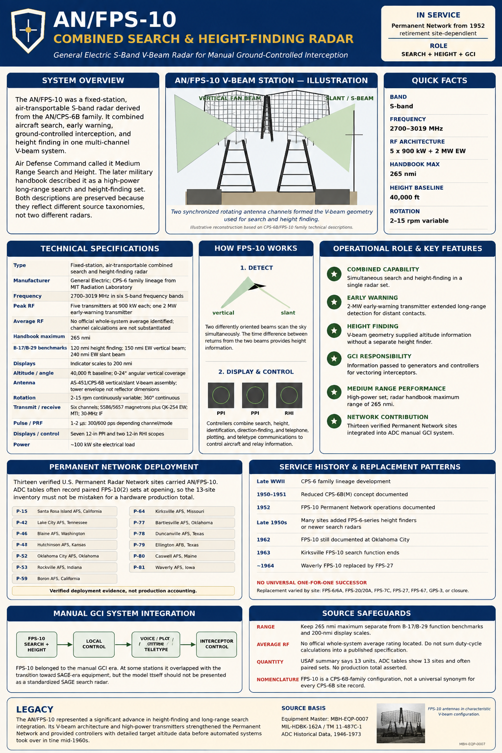
Common Name: Combined Search and Height-Finding Radar. No single official nickname located. Contemporary and later Air Force sources usually identify it simply as the AN/FPS-10.
System Family: ADC Permanent Radar Network; AN/CPS-6B family; manual ground-controlled interception
Equipment Category: Fixed-station, air-transportable S-band combined search and height-finding radar
Primary service: United States Air Force
Primary command context: Air Defense Command permanent radar network and manual ground-controlled-intercept system
Frequency Band: S-band
Frequency MHz: 2700 to 3019 MHz in six frequency bands, one for each transmitter channel
RF sources: Type 5586 and 5657 tunable magnetrons, plus a QK-254 magnetron for the early-warning channel
Pulse width: 1 microsecond at 600 pulses per second, or 1 or 2 microseconds at 300 pulses per second; early-warning transmitter 2 microseconds
Pulse repetition rate: 600 or 300 pulses per second; early-warning transmitter 300 pulses per second
B-17/B-29-type target benchmark ranges: 120 nautical miles for height finding, 150 nautical miles on the early-warning vertical beam, and 240 nautical miles on the early-warning slant beam
Indicator range scales: 0-50, 0-100, and 0-200 nautical miles
Height-finding capability: 40,000 feet
Vertical coverage: 0 to 24 degrees angular
Horizontal coverage: 360 degrees continuous rotation
Antenna rotation: 2 to 15 rpm, continuously variable
Vertical-beam horizontal beamwidth: 1 degree
Vertical-beam vertical beamwidth: 2.2 degrees lower beam, 4.2 degrees middle beam, 21 degrees upper beam
Slant-beam horizontal beamwidth: 0.8 degree
Slant-beam vertical beamwidth: 7.7 degrees lower beam, 24 degrees upper beam
Receiver bandwidth: 2.0 MHz
Intermediate frequency: 30 MHz
Indicators: Seven 12-inch PPI scopes and two 12-inch RHI scopes in the FPS-10 configuration described by MIL-HDBK-162A
Principal antenna/tower assembly: AS-451/CPS-6B in Arctic Tower AB-451/CPS-6B
System classification: ADC described AN/FPS-10 as "Medium Range Search and Height." MIL-HDBK-162A described the same equipment as a high-power, long-range search and height-finding radar for early warning and GCI. Both source contexts are retained rather than forcing one terminology into the other.
Peak Power: 900 kW peak from each of five transmitters; 2 MW peak early-warning transmitter
Average Power: No single official whole-system average RF rating identified. Individual-channel duty-cycle averages can be calculated, but are not substituted for an official rating.
Radar Manufacturer: General Electric Company. The system was derived from the AN/CPS-6 family developed at the Massachusetts Institute of Technology Radiation Laboratory, with General Electric developing and producing the AN/CPS-6A and AN/CPS-6B family in Syracuse, New York.
Primary Role: Aircraft early warning, air surveillance, ground-controlled interception, and height finding
Detection Range: 265 nmi handbook maximum; B-17/B-29 benchmark: 120 nmi height finding, 150 nmi EW vertical beam, 240 nmi EW slant beam; indicator scales to 200 nmi
Altitude Coverage: 40,000 ft; 0-24 degrees angular vertical coverage
Antenna Type & Dimensions: AS-451/CPS-6B vertical/slant-beam antenna assembly in AB-451/CPS-6B Arctic Tower; handbook overall tower/assembly envelope 684 in high by 720 in wide, not reflector dimensions
Antenna Rotation Rate: 2-15 rpm continuously variable; 360-degree continuous rotation
Transmitter & Receiver: Six S-band channels; 5586/5657 tunable magnetrons plus QK-254 EW magnetron; 1-2 microsecond pulse modes; 300/600 pps; MTI; 2 MHz receiver bandwidth; 30 MHz IF; seven 12-in PPI and two 12-in RHI scopes
Power Requirements: 120/208 VAC, 60 Hz, 3-phase, 4-wire; approximately 100 kW
Introduced: CPS-6 lineage developed in late World War II; reduced CPS-6B(M) concept documented by 1950-1951; permanent-network FPS-10 operations documented from 1952
Retired: Site-dependent. Many sets were replaced in the late 1950s and early 1960s; documented persistence includes Oklahoma City to about 1962, Kirksville to 1963, and Waverly to about 1964
Replaced: Reduced-scale derivative/configuration of AN/CPS-6B rather than a universal site predecessor replacement
Replaced By: Site-specific combinations including AN/FPS-6/6A height finders and AN/FPS-20/20A, AN/FPS-7C, AN/FPS-27, AN/FPS-67, GPS-3, and other later search systems
Service era in the continental permanent network: Documented from 1952 into the early 1960s, with site-specific persistence into approximately 1964
Associated Systems: AN/CPS-6B; AN/FPS-6/6A; AN/FPS-20/20A; AN/FPS-7C; AN/FPS-27; AN/FPS-67; AN/GPS-3; MTI; identification, video-mapping, direction-finding, telephone and teletype systems
Preserved Examples: No complete preserved U.S. AN/FPS-10 system confirmed in reviewed public sources. Extensive station photography, diagrams, site remains, and technical documentation survive.
Equipment Identity
The AN/FPS-10 belonged to the first generation of permanent Cold War air-defense radars that replaced the improvised Lashup network with a more capable national warning system. Its historical significance is easy to miss because it was neither a revolutionary stand-alone design nor one of the visually famous late-1950s SAGE radars. Instead, it was a deliberately reduced configuration of the AN/CPS-6B, a complex combined search and height-finding radar whose lineage reached back to wartime research at the MIT Radiation Laboratory. The Air Force needed the capabilities of the CPS-6B at permanent stations, but not every location required the full controller and display complement of the larger set. The reduced configuration became the AN/FPS-10.That lineage explains why the designation can be confusing. The FPS-10 did not merely resemble the CPS-6B in broad concept. The 1965 military handbook lists numerous CPS-6B-designated components inside the FPS-10, including antenna, transmitter-receiver, indicator, power, control, calibrator, moving-target-indicator, and plotting assemblies. The handbook also says directly that the two systems were similar, while identifying practical differences in indicator complement, the absence of B-scan indicators in the FPS-10 configuration, the telephone installation, and the amount of plotting equipment and associated cabling. In effect, AN/FPS-10 was a system-level configuration within the CPS-6B technical family rather than a wholly new radar built around unrelated hardware.
This family relationship also requires caution with site histories. Some station records describe early equipment as AN/CPS-6B, others as AN/FPS-10, and some explicitly explain that equipment initially called CPS-6B was later identified as FPS-10.
Development Lineage
The technical roots of AN/FPS-10 lay in the late World War II effort to create a microwave radar able to combine wide-area search with altitude determination. The MIT Radiation Laboratory developed the original AN/CPS-6 family, and General Electric subsequently developed and produced the A and B versions at Syracuse, New York. The CPS-6 concept used multiple S-band beams and a conspicuous paired antenna arrangement, including a slanted antenna component that made height determination possible. The design gave an air-defense station one integrated radar family for detecting aircraft, establishing azimuth and range, and obtaining altitude information needed for interception.The immediate postwar air-defense situation made that capability strategically important. Air Defense Command reactivated in 1946 with very little operational radar infrastructure, while Soviet long-range bomber capability and the Soviet atomic program steadily changed the warning problem. The temporary Lashup network used stored wartime sets at rapidly prepared locations, but the Air Force regarded it as an interim measure. The permanent network approved in the late 1940s was intended to provide durable stations, dedicated communications, and newer radar equipment able to support continuous warning and ground-controlled interception.
An ADC history of air defense through June 1951 records the administrative origin of the FPS-10 especially clearly. The command planned to retain a large version of the CPS-6B configuration in areas with dense air traffic or the greatest likelihood of hostile penetration, while creating a reduced-scale version with fewer controller positions for less demanding locations. That reduced version was initially called AN/CPS-6B(M) and later became AN/FPS-10. This was not merely a cost-cutting label change. It was a deliberate attempt to tailor a complex radar and controller installation to different operational loads across the growing permanent network.
The Korean War made deployment more urgent. After North Korea invaded South Korea in June 1950, U.S. leaders feared the conflict might precede a wider Soviet attack. Permanent-network construction accelerated, but radar delivery, site construction, spare parts, and trained personnel remained serious bottlenecks. A strike at General Electric's radar fabrication plant was among the delays described in the Air Force historical record. The FPS-10 therefore emerged during a period when the United States was trying to build a national radar system faster than facilities, equipment, and manpower could comfortably support.
Manufacturer and Production Context
MIL-HDBK-162A identifies General Electric Company as the manufacturer for AN/FPS-10. That designation is consistent with the CPS-6 family history, which places development and production of the CPS-6A and CPS-6B at General Electric's Syracuse operation. The underlying concept had originated at MIT's Radiation Laboratory, so development credit and manufacturing credit should not be collapsed into a single statement. MIT supplied the scientific and engineering lineage. General Electric became the industrial producer of the mature family and is the manufacturer named in the military equipment handbook for FPS-10.The production quantity is less straightforward than many later summaries imply. The 1997 Air Force history Searching the Skies states that thirteen FPS-10 units served within the first permanent network. The ADC station tables, however, identify thirteen permanent-network locations using FPS-10 and frequently show the notation FPS-10(2), indicating two sets at a station. Station histories for places such as Santa Rosa Island, Blaine, Hutchinson, Kirksville, and Waverly also describe pairs of FPS-10 radars. Because the Air Force narrative may have used "units" as shorthand for station installations rather than a literal count of hardware, a total production figure cannot be safely derived from the thirteen-site statement alone.
Purpose and Operational Role
The FPS-10's purpose was to detect approaching aircraft, establish their position, supply altitude information, and support controllers who directed interceptor aircraft toward unidentified or hostile targets. MIL-HDBK-162A identifies aircraft early warning and ground-controlled interception as the core applications. Those functions placed the set directly in the operational chain from sensor to command center to fighter. A radar scope trace became useful military information only when an operator detected it, identified or classified it, plotted its movement, communicated the track, and, when necessary, helped guide a fighter to the target.ADC's compact equipment inventory calls FPS-10 a medium-range search and height radar. The 1965 handbook calls it high-power and long-range, with a maximum range of 265 nautical miles. These descriptions are not necessarily contradictory because they arise from different classification schemes and different moments in the radar network's technological development. By the standards of the early permanent network, FPS-10 could perform long-range warning work. In ADC's later retrospective taxonomy, it fell below the long-range systems that came to define the mature SAGE-era network. The history therefore preserves both labels and explains the context rather than choosing one and discarding the other.
How the Radar Worked
The FPS-10 transmitted short pulses of S-band radio energy and measured the time required for echoes to return from aircraft. The bearing of the rotating antenna established azimuth, while pulse travel time established range. The system's several transmitter channels and paired beam geometry allowed it to do more than place a target on a flat map. The vertical-beam and slant-beam arrangement generated different elevation coverage, giving operators information from which target height could be determined and displayed on range-height equipment.The handbook's beam data shows how deliberately the coverage was shaped. The vertical-beam antenna produced several vertical lobes, with a narrow lower beam and progressively broader middle and upper coverage. The slant-beam antenna likewise used lower and upper vertical patterns while maintaining a narrow horizontal beam. This geometry helped provide usable coverage close to the horizon while also extending upward through a large angular volume. It was a mechanically rotating solution to a three-coordinate problem that later radar generations would solve with more sophisticated stacked-beam, frequency-diversity, and eventually electronically scanned architectures.
The station operator did not see one universal "range" for the radar. MIL-HDBK-162A gives a 265-nautical-mile maximum range in its functional description, but its target-specific technical data gives 120 nautical miles for height finding against a B-17/B-29-type target, 150 nautical miles on the early-warning vertical beam, and 240 nautical miles on the early-warning slant beam. The indicator scales extended only to 200 nautical miles. These figures describe different things and should never be collapsed into one simple detection range. Maximum system capability, a benchmark target on a particular beam, and the range scale displayed to an operator answer different questions.
Transmitter and Receiver Characteristics
The FPS-10 used six frequency bands between 2700 and 3019 MHz. Five transmitters were rated at 900 kW peak power, while the early-warning transmitter was rated at 2 MW peak. The handbook identifies type 5586 and 5657 tunable magnetrons for the regular channels and a QK-254 magnetron for the early-warning channel. Pulse modes included one microsecond at 600 pulses per second and one or two microseconds at 300 pulses per second. The early-warning transmitter used a two-microsecond pulse at 300 pulses per second.A single average RF power rating is not supplied by the handbook, and one should not be invented by adding the transmitter peak ratings together. The channels do not operate as one six-transmitter continuous source, and duty cycle differs by pulse mode. A calculated average can be produced for an individual transmitter if pulse width and repetition rate are specified, but that would be a derived engineering value, not an official system rating. For the equipment master, the authoritative peak values are therefore preserved while the average-power field is explicitly treated as unresolved at the whole-system level.
The receiver path used a 2 MHz bandwidth and a 30 MHz intermediate frequency. Moving-target indication was part of the system, helping operators suppress returns from fixed terrain and other stationary clutter so moving aircraft could stand out more clearly. The handbook also identifies provisions for advanced filtering intended to reduce the delay that came from sending raw plots through a separate filter room. These features show that FPS-10 was not just a powerful transmitter and antenna. It was an integrated detection and presentation system built to improve the quality and speed of information available to controllers.
Displays and Operator Positions
The FPS-10 configuration described in MIL-HDBK-162A included seven 12-inch plan-position-indicator scopes and two 12-inch range-height-indicator scopes. The PPI displays presented range and azimuth in map-like form around the station, while the RHI displays supported the vertical dimension needed for altitude determination. Indicator range scales of 50, 100, and 200 nautical miles let operators select the viewing scale suited to local or broader surveillance work.The smaller display complement is central to the distinction between FPS-10 and CPS-6B. The handbook says CPS-6B had more indicators and that FPS-10 omitted the B-scan indicators found in the larger configuration. The two systems also differed in telephone equipment and plotting-equipment quantities. This confirms the original ADC planning concept of a reduced-scale CPS-6B installation for locations where fewer controller positions were adequate. The FPS-10's identity was therefore partly organizational. It packaged a common radar family into a smaller operational station.
Typical Installation and Physical Layout
The handbook recommended installing the radar at the highest available location with sufficient room for an operations building, a separate power building, and the Arctic tower. This requirement helps explain the remote ridges, coastal hills, islands, and elevated plateaus chosen for many permanent-network stations. Radar horizon mattered. A set with hundreds of miles of theoretical range could not see low aircraft through terrain or the curvature of the earth, so local topography remained one of the strongest determinants of actual coverage.The antenna group was mounted in Arctic Tower AB-451/CPS-6B. The handbook's component table identifies Antenna Assembly AS-451/CPS-6B and gives an overall assembly dimension of 684 inches high and 720 inches wide when the tower and building are included. Those figures describe the installation envelope, not a reflector face measurement, so they should not be repeated as antenna-dish dimensions. The tower protected a complex rotating antenna and associated equipment while supporting operation in severe weather.
The indicator and control group occupied the operations building, while power units were housed separately in the power building. Cable ducts or troughs ran below floor level through the buildings and tower. The installation instructions even specified cable-laying order, with heavy cables placed first and coaxial and high-voltage pulse cables later. Such details make clear why a permanent radar station was much more than an antenna on a hill. It was a specialized electrical, communications, maintenance, and operations complex whose physical layout was dictated by high voltage, RF signal integrity, operator workflow, and continuous readiness.
The handbook illustration reinforces this point. Its cutaway layout labels an indicator room, operations room, maintenance room, projection room, telephone room, teletype room, message center, movements and briefing room, triangulation room, transmitter-receiver control assembly, power distribution, utility power supply, and a passageway to the antenna tower. Even if individual stations varied, the diagram captures the functional ecosystem required to turn radar energy into operational air-defense decisions.
Power and Sustainment
MIL-HDBK-162A lists a 100 kW electrical requirement at 120/208 volts AC, 60 Hz, three-phase, four-wire. The principal-component list also includes motor-generators, power supplies, power-control equipment, and a government-furnished diesel power unit. A station therefore required dependable commercial or base power plus backup generation, distribution equipment, fuel, cooling, and trained technicians. Radar readiness depended as much on power and maintenance as on transmitter peak power.The CPS-6 family had a reputation for complexity, and early ADC leaders worried about continuous operation under parts shortages and limited maintenance experience. Those concerns mattered to FPS-10 because it inherited so much CPS-6B hardware. A high-power multi-channel radar could be tactically impressive and still fail as an air-defense asset if magnetrons, modulators, motors, bearings, scopes, cooling systems, or power equipment were unavailable. The reduced FPS-10 configuration lowered the controller and display burden, but it did not turn the underlying radar into a simple unattended sensor.
Integration with Communications and Ground-Control Interception
The FPS-10 was built as part of a communications network, not as an isolated observing instrument. The handbook provides terminals for voice, code or teletype, and radio or wire communications, and provisions for direction finding, identification equipment, and video mapping. These capabilities supported the manual air-defense system in which a radar station tracked aircraft, passed plots to a regional control point, and either performed ground-controlled interception itself or supplied data to controllers elsewhere.Searching the Skies describes the permanent network as labor intensive. At a regional center, information from radar stations and other sources could be transferred manually to large plotting boards. Controllers used the combined picture to vector fighters, while higher command centers received information by telephone and teletype. The FPS-10 belonged to this human-centered architecture. Its operators, plotters, communications technicians, and controllers were as essential as its magnetrons and antennas.
Identification was a constant operational problem. A radar echo did not automatically announce whether an aircraft was friendly, commercial, unknown, or hostile. Optional identification equipment and direction-finding support helped resolve tracks, while the broader Air Defense Identification Zone system used radio interrogation and visual identification by fighters when necessary. This explains why FPS-10 had to coexist with extensive communications equipment and why a station needed multiple controller and plotting positions rather than a single radar operator.
Relationship to SAGE
The FPS-10 was not designed as a native SAGE-compatible radar. It belonged to the manual permanent network built before SAGE computerized the continental air-defense command-and-control system. Searching the Skies places the FPS-10 immediately before its discussion of SAGE-compatible search radars, which included later systems developed specifically to feed the automated network and resist electronic countermeasures more effectively.That did not mean every FPS-10 disappeared the moment a station joined SAGE. Kirksville, for example, began SAGE operations in 1959 while a remaining FPS-10 continued in service until 1963. Oklahoma City and Waverly likewise retained FPS-10 equipment into periods when the broader air-defense system was rapidly automating. The transition was incremental. A station might receive a new height finder first, retain an older search set temporarily, add a newer long-range radar later, and only then remove the final FPS-10 equipment.
Electronic Countermeasures and Operational Testing
The early Cold War forced ADC to consider not only whether radar could detect a bomber, but whether it could continue to detect one in a jamming environment. The FPS-10 had tunable magnetrons across several frequency bands, moving-target indication, and filtering features, but it preceded the later generation of purpose-built frequency-diversity radars developed after Project LAMPLIGHT highlighted the vulnerability of the network to electronic countermeasures. In this sense, FPS-10 occupied an important middle stage between wartime microwave radar and the more specialized anti-jam systems of the SAGE era.CONAD historical material from the mid-1950s also places FPS-10-type S-band radars in exercises and tests involving simulated air-defense radar operations and electronic countermeasures. Such activity shows that the radar family was not merely a static peacetime warning device. It was part of the training and evaluation environment through which Continental Air Defense Command measured how well the defensive network could function against increasingly sophisticated bomber tactics and electronic attack.
Deployment in the Permanent Radar Network
ADC equipment tables identify thirteen permanent-network locations with FPS-10 service. These were Santa Rosa Island, California, P-15; Lake City, Tennessee, P-42; Blaine, Washington, P-46; Hutchinson, Kansas, P-47; Oklahoma City, Oklahoma, P-52; Rockville, Indiana, P-53; Boron, California, P-59; Kirksville, Missouri, P-64; Bartlesville, Oklahoma, P-77; Duncanville, Texas, P-78; Ellington Air Force Base, Texas, P-79; Caswell, Maine, P-80; and Waverly, Iowa, P-81. This list is especially valuable because it converts the later Air Force statement about thirteen permanent-network FPS-10 installations into named, source-controlled site evidence.Many of those sites initially operated paired FPS-10 sets. Santa Rosa Island's 669th Aircraft Control and Warning Squadron operated two in 1952. Blaine's 757th began with a pair in January 1952. Hutchinson's 793d began operating a pair in May 1952. Kirksville's 790th activated a pair in April 1952, and Waverly likewise began with paired FPS-10 equipment. The pair arrangement reflected the combined search/height-finding role and the station-level configuration inherited from the CPS-6 family.
The western stations illustrate the radar's role in replacing provisional defenses. At Santa Rosa Island, activation of the permanent radar site allowed Lashup stations at Camp Cooke and Port Hueneme to close. The island station later added an FPS-3, GPS-3, and MPS-14 before its squadron moved to Lompoc in 1963. Blaine, positioned near the Canadian border and Puget Sound approaches, moved from FPS-10 equipment to FPS-20 search and FPS-6-series height finders, then to the much larger FPS-24 frequency-diversity radar.
Hutchinson shows a different path. The radar site was collocated with the former Naval Air Station south of the Kansas city and began with FPS-10s in 1952. By the end of the decade it was performing air-traffic-control duties for the Federal Aviation Agency while newer Air Force radar replaced the FPS-10 family. The later radar site survived as part of the civil and joint-surveillance system. The FPS-10 itself was gone, but the location's continued use demonstrates how early permanent-network infrastructure sometimes outlived several generations of electronics.
Longer-Lived FPS-10 Stations
Kirksville provides one of the clearest examples of a phased transition. The 790th AC&W Squadron began with two FPS-10 radars in April 1952. One set performing the height-finding function was phased out in 1958 when an FPS-6A arrived, while the other remained as the search radar until 1963. An FPS-7C then replaced it. This sequence shows why a single "FPS-10 retirement date" is misleading. The same station could retire one member of the pair years before the other.Waverly remained an FPS-10 site even longer. ADC tables show FPS-10 with FPS-6-series height finders in 1959 and 1961, and still record FPS-10 in 1963. Station histories place final replacement of the remaining FPS-10 search function by an FPS-27 in 1964. Waverly therefore represents the late edge of continental FPS-10 service, by which time the radar had been overtaken by equipment designed for the automated SAGE environment and improved electronic-countercountermeasures performance.
Oklahoma City likewise demonstrates gradual replacement. The station opened with a pair of FPS-10s and later added FPS-6 height finding. ADC tables still show an FPS-10 in 1962 together with an FPS-67, while the following year's equipment list no longer includes it. These overlaps are a reminder that radar modernization was performed while the defense mission continued. Engineers could not simply shut down a sector for several years while new equipment was installed.
Texas and the Southern Approaches
Duncanville, Ellington, and Bartlesville placed FPS-10 equipment across the south-central portion of the permanent network. Duncanville's 745th AC&W Squadron operated a CPS-6B/FPS-10-family set beginning in 1952. The station later passed to Army use for control of Nike missile defenses around Dallas and Fort Worth. The radar designation boundary is especially visible there because specialist histories describe an AN/CPS-6B later called an AN/FPS-10, reinforcing the need to preserve contemporary nomenclature rather than assume two unrelated systems.Ellington Air Force Base combined FPS-10 with other radar types during a particularly fluid period. ADC records show paired FPS-10s, then combinations involving FPS-8, GPS-3, and FPS-6. By 1961 the site had moved to an FAA ARSR-1A long-range radar with FPS-6 height finding. The transition illustrates how military air-defense and civil air-traffic-control requirements increasingly intersected around major population and aviation centers even though FPS-10 itself was not a purpose-built FAA system.
Bartlesville had a shorter operational life. It opened with two FPS-10s, later operated FPS-6 height-finding equipment with a remaining FPS-10, and ceased operations around the end of the 1950s or beginning of the 1960s depending on whether one follows operational-cessation or squadron-inactivation dates. Such differences are common in radar histories. A radar may stop transmitting before a unit formally inactivates, and property may remain under military control after the operational mission has ended.
Replacement by Specialized Search and Height-Finding Systems
The FPS-10's combined role was attractive when the permanent network was being built rapidly, but the Air Force soon moved toward more specialized equipment. The AN/FPS-6 family became the standard high-performance height finder. Search duties shifted to FPS-20-series, FPS-7, FPS-27, FPS-24, FPS-67, and other systems depending on site and sector. These later combinations provided higher altitude coverage, better compatibility with SAGE, improved reliability or anti-jam performance, and more flexible modernization paths.The site sequences make this specialization visible. At Kirksville and Waverly, an FPS-6-series height finder arrived while one FPS-10 remained in the search role. At Blaine, FPS-20 replaced the FPS-10 search function before the station advanced to FPS-24. At Hutchinson, FPS-20 and later FPS-66-series equipment took over search duties. At Santa Rosa Island and Ellington, GPS-3 and other radar types overlapped with or replaced the FPS-10 family. The technology did not vanish in one synchronized national changeover. It was displaced station by station as construction, funding, electronics, and operational priorities allowed.
Civil Air-Traffic-Control Connections
The FPS-10's direct civil-aviation service is less well documented than the joint-use careers of some of its successor radars. It would therefore be inaccurate to describe the system itself as a standard FAA radar. The important connection is institutional and geographic. Several sites that began with FPS-10 later became FAA or joint-use radar locations, including Hutchinson and other stations whose military surveillance role was gradually blended with peacetime air-traffic-control requirements.This transition reflects the broader value of the permanent-network sites. They occupied high terrain, had reliable power and communications, and already covered major air routes and metropolitan approaches. Once the military installed newer radar, the site infrastructure could support civil surveillance with little need to recreate the entire physical plant. The FPS-10 thus helped establish some radar locations that remained useful long after the original electronics had been removed.
Variants, Related Systems, and Designation Boundaries
The most important related system is AN/CPS-6B. The FPS-10 used so much CPS-6B hardware that the 1965 handbook's principal-components list is dominated by CPS-6B type designations. The Air Force's own history called FPS-10 a stripped-down CPS-6B, while its earlier administrative history explained the reduced-scale controller concept that led from CPS-6B(M) to FPS-10. The relationship is therefore direct and well supported.That does not mean CPS-6B and FPS-10 were interchangeable labels in every record. The handbook specifically distinguishes their indicator complements, B-scan provision, telephone-system supply, and plotting equipment. Station histories can also reflect local modification or reclassification over time. For equipment-reference purposes, the safest rule is to preserve an installation's source designation and use the family relationship to explain it, rather than replacing the designation automatically.
The FPS-10 also belongs in a larger chain of early ADC radar modernization. AN/FPS-6 and FPS-6A height finders often replaced the FPS-10's height function. FPS-20 and FPS-20A, FPS-7C, FPS-27, FPS-67, and other search radars replaced its surveillance function at different stations. GPS-3 appeared at several of the same sites but was a stripped FPS-8 family configuration, not a variant of FPS-10. The shared "stripped" language in historical summaries should not be allowed to blur the two unrelated reduction programs.
Operational Reliability and Human Workload
The FPS-10 era was defined by continual human interpretation. Radar operators watched scopes, height-finder operators worked RHI presentations, plotters transferred tracks, controllers used radio to direct interceptors, and communications personnel kept land lines, teletype, and radio circuits operating. Maintenance crews worked on high-voltage modulators, magnetrons, motors, scopes, generators, antenna drives, and cooling systems. The operational system was therefore a combination of electronics and skilled labor.This human workload is one reason the later SAGE system was so transformative. Manual track reporting created delay at every step, especially when radar plots passed from station to regional center to higher headquarters. FPS-10's provisions for more advanced filtering and remote operation reduced some local delays, but the fundamental command system remained manual. The radar was a capable sensor operating inside an information architecture that automation was already beginning to outgrow.
Preserved Equipment and Surviving Evidence
No complete, publicly documented AN/FPS-10 installation or intact radar set has been confirmed as preserved in the United States. This should not be confused with survival of former FPS-10 sites. Some locations remain active radar facilities, public parks, reused military properties, or altered former stations. Other sites, including Santa Rosa Island, were demolished. Surviving towers, buildings, or concrete features at a former station do not by themselves prove that original FPS-10 hardware remains.
P-15 Santa Rosa Island Air Force Station, California
P-42 Lake City Air Force Station, Tennessee
P-46 Blaine Air Force Station, Washington
P-47 Hutchinson Air Force Station, Kansas
P-52 Oklahoma City Air Force Station, Oklahoma
P-53 Rockville Air Force Station, Indiana
P-59 Boron Air Force Station, California
P-64 Kirksville Air Force Station, Missouri
P-77 Bartlesville Air Force Station, Oklahoma
P-78 Duncanville Air Force Station, Texas
P-79 Ellington Air Force Base, Texas
P-80 Caswell Air Force Station, Maine
P-81 Waverly Air Force Station, Iowa
Chronology
- 1944-1945 MIT Radiation Laboratory work on the AN/CPS-6 family established the technical lineage from which AN/FPS-10 later developed.
- 1945 Early AN/CPS-6 equipment entered production in the closing period of World War II.
- 1946-03-27 Air Defense Command was reactivated and given responsibility for building an integrated continental air-defense system.
- 1948-10 Defense Secretary James Forrestal approved the reduced permanent-network concept that evolved into a seventy-five-station radar system.
- 1949-12-02 The Air Force directed the Army Corps of Engineers to begin construction of the first permanent-network stations.
- 1950 General Electric's AN/CPS-6B entered the permanent-network equipment pipeline while ADC developed a smaller-controller-position configuration for less demanding sites.
- 1950-1951 ADC records identify the reduced configuration first as AN/CPS-6B(M) and later as AN/FPS-10.
- 1950-06-25 The Korean War began, sharply increasing pressure to accelerate U.S. air-defense construction and radar deployment.
- 1951 Permanent-network construction and radar procurement continued despite shortages of equipment, parts, manpower, and construction capacity.
- 1952-01 Blaine AFS, Washington, began operation with a pair of AN/FPS-10 radars.
- 1952-04 Kirksville AFS, Missouri, activated a pair of AN/FPS-10 radars with the 790th Aircraft Control and Warning Squadron.
- 1952-05 Hutchinson AFS, Kansas, began operating a pair of AN/FPS-10 radars.
- 1952 Santa Rosa Island AFS, California, operated two AN/FPS-10 radars under the 669th Aircraft Control and Warning Squadron.
- 1952 Oklahoma City, Rockville, Boron, Bartlesville, Duncanville, Ellington, Caswell, Waverly, Lake City, and other permanent-network stations entered the FPS-10 deployment record.
- 1955 Several FPS-10 stations began receiving additional or replacement search radars as ADC modernization accelerated.
- 1956-1958 AN/FPS-6-series height finders increasingly replaced the FPS-10 height-finding function at permanent-network stations.
- 1958 Kirksville phased out one FPS-10 from the height-finding role after installation of an AN/FPS-6A while retaining the other FPS-10 for search.
- 1958-1959 Many FPS-10 locations transitioned to FPS-20-series or other newer search radars.
- 1959 Blaine transitioned from FPS-10 to FPS-20 search with FPS-6-series height finders.
- 1959 Hutchinson was performing FAA air-traffic-control duties while newer search equipment replaced its earlier FPS-10 pair.
- 1959 Boron no longer relied on its original FPS-10 pair as newer radar entered service.
- 1960 Several early FPS-10 sites had closed or removed the type, while others retained a single set during modernization.
- 1961 Kirksville, Oklahoma City, Rockville, and Waverly illustrate the continued overlap between older FPS-10 equipment and the emerging SAGE-era network.
- 1962 ADC tables still record an AN/FPS-10 at Oklahoma City together with newer radar equipment.
- 1963 Kirksville replaced its remaining FPS-10 search radar with an AN/FPS-7C.
- 1963 ADC equipment tables still show AN/FPS-10 at Waverly, Iowa.
- 1964-04-01 MIL-HDBK-162A data for AN/FPS-10 lists the set as USAF Standard and records its detailed technical configuration.
- 1964 Station histories place replacement of Waverly's remaining FPS-10 search function by an AN/FPS-27, marking the late edge of documented continental permanent-network service.
- 1965-12-15 MIL-HDBK-162A consolidated the FPS-10 technical description, component data, site layout, performance figures, and relationship to AN/CPS-6B.
- 1997-06 Air Combat Command's Searching the Skies summarized AN/FPS-10 as a stripped-down AN/CPS-6B and stated that thirteen installations or units served in the first permanent network.
- Present No complete preserved AN/FPS-10 system has been confirmed in the reviewed public record, but extensive technical documentation and site photography survive.
Sources & References
- PDF MIL-HDBK-162A, Military Standardization Handbook, United States Radar Equipment, Volume 1 Source for authoritative AN/FPS-10 technical specifications, installation architecture, components, manufacturer, and relationship to AN/CPS-6B.
- WEB David F. Winkler, Searching the Skies: The Legacy of the United States Cold War Defense Radar Program, Headquarters Air Combat Command, June 1997 Source for the permanent-network context, CPS-6 lineage, AN/FPS-10 relationship to CPS-6B, and the Air Force's statement that thirteen served in the first permanent network.
- PDF Aerospace Defense Command, Historical Data of the Aerospace Defense Command, 1946-1973 Source for ADC classification of AN/FPS-10 as Medium Range Search and Height and for site-by-site equipment sequences.
- PDF Air Defense Command, The Air Defense of the United States, a Study of the Work of ADC and its Predecessors through June 1951 Source for the reduced-scale AN/CPS-6B(M) concept that became AN/FPS-10 and for early permanent-network planning.
- WEB Online Air Defense Radar Museum, Radar Equipment Index Specialist cross-check for equipment relationships, SAGE compatibility, nomenclature, and links to station photography.
- WEB Online Air Defense Radar Museum, Santa Rosa Island AFS, California Source for the 669th AC&W Squadron, paired FPS-10 operation, replacement sequence, and photographs.
- WEB Online Air Defense Radar Museum, Blaine AFS, Washington Source for paired FPS-10 operation beginning in January 1952, later replacement, station use, and photographs.
- WEB Online Air Defense Radar Museum, Hutchinson AFS, Kansas Source for paired FPS-10 operation beginning in May 1952, FAA air-traffic-control transition, later radar sequence, and photographs.
- WEB Online Air Defense Radar Museum, Kirksville AFS, Missouri Source for the paired FPS-10 configuration, 1958 height-finder replacement, 1963 search-radar replacement, SAGE transition, and photographs.
- WEB Online Air Defense Radar Museum, Duncanville AFS, Texas Source for CPS-6B/FPS-10 designation history, later Nike-control use of the site, and photographs.
- WEB MobileRadar.org, Radar System Descriptions Specialist technical cross-check for CPS-6B/FPS-10 family configuration and beam/range characteristics.
- PDF RFCafe mirror of MIL-HDBK-162A Independent accessible mirror used to cross-check the handbook's AN/FPS-10 performance and installation tables.