
AN/FPS-95 Cobra Mist Over-the-Horizon Radar
Type: Fixed HF over-the-horizon backscatter radar
Program: System 441A / Cobra Mist
Location:
Orford Ness, Suffolk, England
Intended role: Long-range aircraft and missile observation
Result: Tested but never
achieved reliable operational surveillance
Overview
The AN/FPS-95 was a United States Air Force high-frequency, over-the-horizon backscatter radar built at Orford Ness on the east coast of England. Known by the program name System 441A and the final code name Cobra Mist, it was intended to observe aircraft and missile activity far beyond the geometric horizon by transmitting energy toward the ionosphere and receiving energy scattered back from the earth and from moving targets. It was not a conventional rotating search radar, and its enormous fixed antenna was unlike the dishes associated with most Air Defense Command stations.
Cobra Mist grew from the confidence created by the Naval Research Laboratory's MADRE experimental radar, which had detected aircraft at ranges of roughly 1,500 to 2,000 nautical miles and had observed missile launches from Cape Canaveral. The Air Force sought to turn that experimental promise into an intelligence sensor overlooking Eastern Europe and the western Soviet Union. The resulting system was more powerful and more ambitious than MADRE, but it also demanded a degree of subclutter visibility that had not been demonstrated by the earlier equipment.
The radar was designed for operation from 6 to 40 megahertz, with selectable pulse widths, pulse repetition frequencies, polarizations, elevation beams, and coherent integration times. Its 18 log-periodic antenna strings formed 13 discrete azimuth beams across a 91-degree surveillance sector. Six transmitter amplifiers could together deliver about 3.5 megawatts peak and 300 kilowatts average in the configuration actually achieved, although the original design goals had been 10 megawatts peak and 600 kilowatts average.
AN/FPS-95 never achieved usable operational status. The principal limitation was clutter-related noise, a spectrally spread residue associated with range cells that contained strong earth backscatter. The system needed approximately 80 to 90 decibels of visibility beneath the clutter for its intended aircraft and missile missions, but practical performance was generally limited to about 60 to 70 decibels. A major United States and British investigation tested the transmitter, receiver, signal processor, antenna, ground screen, propagation path, and possible hostile countermeasures without conclusively locating the cause.
The program ended in June 1973 after the joint Scientific Assessment Committee recommended modifications and another year of operational-feasibility testing. United States and British authorities instead concluded that the additional cost was not justified. The radar equipment and antenna were dismantled, while the large operations and transmitter building survived and was reused as a high-power radio transmitting station. The site later passed into private ownership, and portions of the former radar landscape remain legible in foundations, disturbed ground, surviving masts, and the main building.
System identity and designations
AN/FPS-95 was the Joint Electronics Type Designation System name for the radar set. In that designation, AN identifies a standardized electronic installation, F indicates fixed use, P indicates radar, and S identifies detecting or range-and-bearing functions. The designation describes the equipment, not a normal Air Force Station, squadron, or permanent air-defense cantonment. Orford Ness was the single confirmed AN/FPS-95 installation.
System 441A was the broader acquisition and test program that placed the radar, processing chain, displays, computers, supporting instrumentation, and site infrastructure into an overseas operating environment. The code name evolved from Sentinel Fan to Sentinel Mist and finally Cobra Mist. Sources sometimes use AN/FPS-95, System 441A, and Cobra Mist interchangeably, but the distinction matters because a statement about the whole program may include equipment and organizations beyond the formal radar-set boundary.
The site name also varies. American records often write Orford Ness or Orfordness, while British records use both forms for the shingle spit and later transmitting station. This history uses Orford Ness for the geographic feature and AN/FPS-95 or Cobra Mist for the radar. It does not create a separate equipment identity for the later BBC and Foreign Office radio station, which reused the building and power infrastructure for a different mission.
Representative coordinate: 52.1039 degrees north, 1.5761 degrees east, WGS84 (View on Google Maps). This is an approximate coordinate for the surviving former Cobra Mist main building and later transmitting-station complex, derived from public heritage and mapping records. It is not a surveyed antenna-hub coordinate, a parcel boundary, or a claim that every radar component occupied that point; the original fan array extended broadly east and northeast from the central area.
Strategic origins
High-frequency skywave radar attempts to overcome the line-of-sight limit by directing energy upward at a shallow angle. Refraction in the ionosphere returns part of that energy toward the earth hundreds or thousands of miles away. Ground, sea, aircraft, and missile phenomena can scatter a very small portion back through the ionosphere to the radar. This geometry creates exceptional reach, but it also makes performance dependent on frequency, time of day, solar conditions, ionospheric structure, propagation mode, and the overwhelming strength of earth backscatter.
MADRE demonstrated that coherent Doppler processing could separate moving aircraft or missile signatures from much stronger surface returns. Those successes encouraged the Air Force to plan an operational intelligence radar in Turkey. A Turkish position would have provided useful geometry toward Soviet activity, but the required site was not made available. The program therefore entered a search for another host country and another coastline with an unobstructed look toward the areas of interest.
Britain offered Orford Ness in Suffolk. Its North Sea exposure allowed the antenna to radiate across water before the skywave footprint reached continental Europe, and its bearing geometry covered much of Eastern Europe and the western Soviet Union. The location also had an established military research history, physical isolation, and enough land for a fan antenna measured in thousands of feet, although unexploded ordnance and difficult shingle terrain complicated construction.
The mission requirement was wider than routine air warning. Program documents describe detection and tracking of aircraft, detection of missile and earth-satellite launches, support to current and critical intelligence requirements, and use as a research and development testbed for improved backscatter techniques. Plesetsk and heavily traveled air routes in the western Soviet region were prominent objectives, but the program also sought the knowledge required to make later OTH systems operationally reliable.
Contracting and program management
The Air Force solicited contract-definition proposals in 1964. RCA received the definition award with an approach that closely followed the MADRE concept. After the Turkish site became unavailable, a new 1966 competition addressed an English installation, and RCA's Moorestown, New Jersey organization received the construction contract late that year. The choice made RCA the prime contractor for an unusually large combination of antenna, high-power transmitter, receiving system, digital and analog processing, control equipment, and site integration.
Program management belonged to the Electronic Systems Division of Air Force Systems Command at Hanscom Field, Massachusetts. Engineering responsibility had been assigned to Rome Air Development Center at Griffiss Air Force Base, New York. The Naval Research Laboratory supplied scientific support, and MITRE later assumed a central part in the Design Verification System Testing. This network of organizations combined acquisition authority, radar engineering, experimental science, contractor production, and British host-nation participation.
The planned operational relationship was Anglo-American. The system initially required scientists who could verify its design, develop illumination and tracking procedures, and interpret unfamiliar data. The long-term concept called for a combined Royal Air Force and United States Air Force operating crew. The project therefore did not progress from contractor acceptance directly to ordinary watch operations; it first had to pass a demanding scientific program that would define whether an operational method existed.
In 1969 the Cobra Mist Working Group prepared the DVST plan. Representatives of major United States and British OTH organizations shaped a one-year program, with MITRE and NRL selected in early 1970 to conduct it. The Air Force also formed a DVST Technical Advisory Committee in 1970. Those arrangements recognized that the new radar was simultaneously a deliverable system, a research instrument, and an intelligence prototype whose operating doctrine could not be copied from a conventional search radar.
Orford Ness setting and site preparation
Orford Ness is a long, low shingle spit between the River Ore and the North Sea. Its remoteness aided security and reduced interference with populated areas, but it made transport, utilities, and construction difficult. The site chosen for Cobra Mist had been used as a bombing target, so unexploded-ordnance clearance began before heavy construction. British heritage records place the start of clearance and preparation in 1967, with most building work complete by July 1971 and fitting-out continuing into early 1972.
The antenna required a broad sector of land east of the central hub. A wire-mesh ground screen covered the array area and extended in the propagation direction. Long antenna strings, high supports, underground switching facilities, transmission lines, access roads, drainage, electrical distribution, and a heavily serviced main building transformed the northern part of the spit. The array was a landscape-scale engineered structure rather than an antenna mounted on one tower.
High transmitter power required a new electrical supply from the mainland. Research into the Orford Ness power network describes submarine cables crossing the river and feeding substations in the Cobra Mist building. The same infrastructure later supported the broadcasting station and parts of the wider Orford Ness network. Power conditioning, cooling, grounding, transmitter protection, and continuous technical maintenance were essential because spectral purity had to be preserved many tens of decibels below an enormous transmitted carrier.
The main building contained transmitter and receiver spaces, control and display areas, processing equipment, computer facilities, workshops, utilities, and the interfaces to the antenna field. The underground hub switching matrix selected the active antenna strings, while beam-forming networks in the building established the required phasing. Surviving-building photographs should not be interpreted as showing the original internal arrangement, since post-1973 broadcast conversion removed military equipment and added a different generation of transmitters and antenna feeders.
Antenna geometry
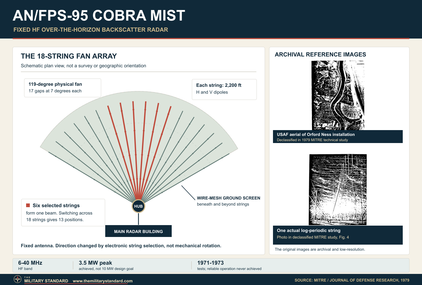
The best declassified technical account describes 18 log-periodic strings radiating like spokes from a central hub. Each string was approximately 2,200 feet long and carried both horizontal and vertical dipoles. Adjacent strings were separated by 7 degrees, producing a 119-degree physical fan. A heritage summary gives somewhat different dimensions and angular spacing, but the MITRE description is preferred for the equipment baseline because it was written by investigators who worked with the radar and includes the complete system parameter tables.
Only six adjacent strings were energized for a given beam. An underground switching matrix at the hub connected the chosen sextet to transmit or receive beam-forming networks in the main building. Changing which six strings participated shifted the beam in azimuth, producing 13 discrete pointing positions. Because five strings were shared between adjacent beams, the system could step through the sector without mechanically rotating any antenna.
The log-periodic geometry allowed one physical string to cover the 6 to 40 megahertz band. At high frequency the electrically active elements were near the hub, where the dipoles were smaller. As frequency decreased, the active region moved outward toward larger elements. This frequency-dependent movement required careful phasing so the six active strings produced a sufficiently planar wavefront and a predictable pointing direction across the band.
The nominal azimuth surveillance sector extended from 19.5 to 110.5 degrees clockwise from true north, a total of 91 degrees. The nominal three-decibel azimuth beamwidth was 7 degrees. Monopulse sum and difference channels were intended to improve bearing accuracy to about 1 degree, but ionospheric tilts could introduce errors of several degrees. Limited pattern measurements also found frequency- and beam-dependent departures in pointing, elevation beam shape, and sidelobe levels.
Vertical and horizontal polarization provided different elevation patterns. Published design values give a vertical-polarization elevation beamwidth of approximately 2 to 10 degrees and a horizontal-polarization range of roughly 8 to 30 degrees. In normal F-layer operation, vertical polarization generally produced a lower takeoff angle and horizontal polarization an upper pattern, allowing the radar to alter illuminated range along with frequency. The choice did not create direct height measurement; it changed propagation geometry.
The antenna gain was approximately 25 decibels. Nominal sidelobe values were about 13 decibels below the main beam for the first sidelobe, 18 decibels for the second, and 20 decibels for others. Actual patterns varied, and some beams squinted inward several degrees.
Array construction and damage
The eighteenth and final antenna string was installed by 10 July 1971, and high-power phasing began on 17 July. Rome Air Development Center aircraft flew pattern-measurement missions from 5 through 17 August while the transmitter operated 10 decibels below full power. All 18 strings were tested at multiple ranges, including sidelobes and backlobes, and the long-range portion concluded early in September.
On 23 September 1971 an upper catenary Nuplaglas rod between mast 38 and string 18 failed. The shock damaged most of masts 38 and 39 above the 120-foot level. The program history states that the rod had previously been rejected by RCA because of a deep transverse cut and should not have been installed. RCA repaired the masts rather than replacing them, while string 18 remained electrically sound.
A separate upper-catenary break on string 13 persisted for several weeks and was repaired by 13 December. Work was aided by a 144-foot extension-ladder fire apparatus that RCA obtained after an Argentine purchaser could not complete an order for two such vehicles. These incidents show the unusual maintenance scale of the array: ordinary antenna work demanded tall access equipment, daylight windows, specialist rigging, and careful control of materials that also affected electrical purity.
Transmitter and exciter
The AN/FPS-95 transmitter covered 6 to 40 megahertz and used six linear distributed amplifiers. Each amplifier fed one of the six strings participating in the selected beam. Operators could vary output over a 20-decibel range by changing exciter drive, and four switchable low-pass filter sets suppressed harmonic energy. The distributed architecture made high power available across the broad HF band without relying on a narrowband final stage.
Original goals called for 10 megawatts peak and 600 kilowatts average. The declassified system tables report about 3.5 megawatts peak and 300 kilowatts average as achieved values. That distinction is essential: 10 megawatts describes the design aspiration and electrical scale, not the demonstrated output entered as the equipment baseline. Even at the lower achieved level, Cobra Mist generated enormous surface clutter and imposed exceptional linearity requirements on every receiving and processing stage.
The exciter supplied cosine-squared, flattened cosine-squared, and sin Mx divided by sin x pulse shapes. Search and tracking pulse widths were selectable from 250 to 3,000 microseconds, with a 6,000-microsecond option for special nonoperational use. Published pulse repetition frequencies include 40, 53.33, 80, and 160 pulses per second, plus a special 10-pulse-per-second setting. One reproduced table appears to contain an optical-recognition error reading 60 rather than 40, so the consistent system summary is used.
An oblique-sounder waveform combined ten 200-microsecond carrier pulses separated by 100 kilohertz. It allowed the radar to examine backscatter as a function of frequency and propagation delay before selecting an operating channel. This capability mattered because the best frequency changed with ionospheric conditions and range. The waveform family therefore supported both target observation and the continuous diagnosis of the medium through which the radar had to operate.
Receiver architecture
The receiver had monopulse sum and difference channels corresponding to the antenna beam-forming outputs. Each used a band-switched front end and in-phase and quadrature conversion to baseband. Analog-to-digital converters then produced digital samples for clutter filtering and subsequent processing. The published radio-frequency bandwidth was 5 kilohertz, narrow enough to define a candidate clear channel yet wide enough to accommodate the coherent pulse spectra used for detection.
Linear dynamic range was specified at 140 decibels. That extraordinary value was required because earth backscatter could stand 80 to 90 decibels above weak moving-target returns, while strong external signals in crowded European HF bands could enter through sidelobes. The signal chain had to preserve small Doppler components without producing intermodulation or cross-modulation products from the overwhelming clutter and interference.
Receiver noise figure varied with frequency. The declassified table gives approximately 14 decibels from 6 to 15 megahertz, 9 decibels from 15 to 23, 8 decibels from 23 to 31, and 7 decibels from 31 to 40. Those values did not alone determine sensitivity because atmospheric, galactic, and human-made HF noise often exceeded internal receiver noise. Clear-channel availability and clutter suppression were more consequential operational constraints.
The analog-to-digital conversion was 18-bit, and the designed clutter rejection was 100 decibels. Extensive tests later cleared the receiver as the principal cause of clutter-related noise under the conditions examined. A minority concern remained that constant-amplitude test signals might not have fully tested converter transient response to time-varying clutter. The investigators could not resolve that narrow hypothesis after the system had been dismantled, so it remains an uncertainty rather than an established cause.
Signal processing
After digitization, samples were stored by range cell and passed through a digital clutter filter that rejected the near-zero-Doppler surface return. The stored data were reconverted to analog form and replayed at accelerated speed through filters matched to Doppler frequency and constant acceleration profiles. This hybrid analog and digital approach allowed a broad family of velocity and acceleration hypotheses to be examined before the next real-time pulse train had finished accumulating.
Selectable coherent integration times were 0.3125, 1.25, 2.5, 5, 10, and 20 seconds. Doppler coverage extended from about 3 hertz to one-half the pulse repetition frequency, while acceleration processing covered up to 20 g. These capabilities were intended to accommodate slow aircraft, fast aircraft, and rapidly changing missile signatures. Longer integration improved sensitivity for stable returns but increased vulnerability to fading, maneuver, acceleration mismatch, and changing propagation.
Raw signals could be recorded on magnetic tape at the converter output for offline analysis or replay through the online chain. MITRE developed an independent offline digital processor, and its results closely matched the noise amplitude, spectrum, and time variation seen in the operational processor. That agreement was important because it made a common post-conversion processing defect unlikely, even though it did not prove that every pre-conversion behavior was faultless.
The site also received a Xerox Sigma V computer on 20 July 1971. Leasing was later judged less economical than purchase, and funds were released in February 1972. A Signal Analysis Subsystem procured by the Army Security Agency from Interstate Electric Corporation was installed in early January 1972. NRL initially expected to integrate the Sigma V and subsystem but limited its role to software, leaving Interstate Electric responsible for the broader integration.
Displays and operator work
Processed outputs included target range, azimuth, velocity, acceleration, amplitude, and time history. Cathode-ray-tube presentations could display selected pairs of those variables, and cameras could preserve the screen image. Data could also be written to magnetic tape or automatically typed. The control consoles therefore combined immediate visual judgment with a substantial experimental recording system intended to support later scientific analysis.
The real-time Doppler-time and Doppler-range displays had only two intensity states, on or off. Operators had to select a threshold that separated target indications from a noise floor that changed with range and faded with propagation. Without a gray scale, a return slightly above threshold appeared much like a much stronger one, while a small change could make a fading aircraft disappear. Offline amplitude-scaled displays produced better results but could not supply the intended real-time intelligence service.
Frequency management was an active operating task. A panoramic receiver and a separate vertical ionospheric sounder helped identify interference and estimate useful frequencies. The radar's oblique sounder examined the actual target-direction path. Operators then balanced clear-channel availability, maximum usable frequency, skip distance, the desired footprint, antenna elevation pattern, and the target mission before beginning a searchlight dwell or a beam scan.
Night operations were especially difficult. Shorter one-hop ranges sometimes required frequencies below the 6-megahertz lower limit, while the 6 to 8 megahertz region was crowded by European shortwave broadcasting. Daytime frequencies above 20 megahertz were often clearer for long-range illumination despite greater D-region absorption. The observed advantage of daytime over nighttime aircraft detection was the opposite of ordinary long-range HF communications expectations and became part of the performance puzzle.
Searchlight and scanning modes
Searchlight mode held the radar on a small region whose approximate location was already known. This maximized data rate and permitted several minutes of careful frequency selection. The mode was intended for a single aircraft, compact formation, missile launch area, or other high-priority objective. It represented the best case for the radar because analysts could use flight plans, intelligence cues, and repeated observations to interpret weak returns.
Scanning mode switched among the 13 azimuth beams and changed illuminated range by selecting polarization and frequency. It was intended to search for unknown targets and share time among missions. Each additional beam and range condition reduced revisit time and forced faster frequency decisions. Because even searchlight detection was marginal, routine broad-area scanning proved essentially nonexistent as an operational capability.
One-hop F-layer coverage was nominally about 500 to 2,000 nautical miles. The minimum resulted from the 6-megahertz lower frequency limit and maximum practical elevation angle. Multihop paths could reach more distant suitable targets, but each additional reflection increased ambiguity, attenuation, and propagation complexity. Range was inferred from signal delay through a changing ionosphere rather than from a straight geometric path.
Nominal azimuth accuracy was approximately 1 degree through monopulse beam splitting, but resolution remained about 7 degrees. Range resolution was also coarse because HF spectrum scarcity constrained pulse bandwidth. A broad azimuth cell and long pulse illuminated a vast surface area, creating a very strong aggregate earth return. The same geometry that delivered strategic reach therefore helped produce the clutter challenge that the processor had to overcome.
Design verification and acceptance
System test was delayed in 1971 by problems with a PDP computer and two transmit-receive switches. By early September the individual faults seemed manageable, but the integrated system still failed to produce meaningful display data. Functional tests began on 29 September after RCA supplied screen-regulator modification kits. Reliability and maintainability testing, which required continuous operation, waited until 15 October because antenna-mast repairs could only be conducted in daylight.
The Air Force accepted the radar from RCA on 9 February 1972, and DVST began the next day. Acceptance meant the contractor had met the applicable turnover criteria; it did not mean the system had demonstrated operational utility. A British coal miners' strike caused a power shortage that suspended testing on 14 February. Testing resumed on 1 March, after which the noise problem increasingly dominated site activity.
The original DVST plan included 12 MITRE aircraft experiments plus NRL work on missile detection and other propagation questions. Only three of the aircraft experiments were completed and formally documented: Experiment 202 on radar aurora, Experiment 405 on track-while-scan feasibility, and Experiment 506 on range and azimuth calibration. Other tasks proved too ambitious for actual system capability or lost their assigned scientists to the noise investigation.
Headquarters directed that the planned one-year DVST end after six months on 10 August 1972. Initial Operational Test and Evaluation with United States Air Forces in Europe began in an attempt to achieve an operational date of January 1973. Combining developmental verification with operational evaluation accelerated the schedule, but it did not remove the underlying technical shortfall. On-site and contractor efforts failed to restore the required detection margin.
Observed aircraft performance
Known-aircraft trials in searchlight mode produced tracks less than half the time even when crews used flight plans and carefully accounted for ionospheric conditions, range ambiguity, and Doppler ambiguity. Tracks were commonly discontinuous because aircraft returns rose above the noise only near favorable points in Faraday-rotation and multipath-fading cycles. Observations of high-density routes near Moscow sometimes yielded few or no detections during otherwise favorable propagation.
Aircraft were generally easier to detect over the Baltic Sea than over land. Returns often became most visible beyond the point of maximum ground backscatter, near the trailing edge of the clutter field. Shorter pulses and higher pulse repetition frequencies tended to improve detection, consistent with a clutter-limited system whose ability to see beneath clutter improved at larger Doppler shifts. These patterns were operational observations, not proof of one physical noise mechanism.
At 22.1 megahertz and a 40-pulse-per-second setting, a 20-hertz Doppler shift represented approximately 264 knots of radial velocity. The nominal unambiguous range was about 2,000 nautical miles. A 512-pulse fast Fourier transform over 12.8 seconds could separate the dominant near-zero-Doppler clutter from moving returns, yet broad excess energy remained across target Doppler bins in the same ranges that contained ground clutter.
The performance deficit was large. Clutter-related noise was frequently 20 decibels and sometimes 30 decibels above the external-noise floor. Instead of the 80 to 90 decibels of subclutter visibility required for the mission, the radar usually delivered only 60 to 70 decibels. That shortfall converted a powerful transmitter and sophisticated processor into a sensor that could sometimes demonstrate a known target but could not provide dependable surveillance.
Range-related and clutter-related noise
Investigators used range-related noise as a broad description for excess energy whose level changed with range. It appeared at short range, in parts of the skip zone before normal ground backscatter, and in range cells containing earth returns. Clutter-related noise was the especially damaging component that tracked the presence and strength of surface clutter. When the transmitters were turned off, the range structure vanished and ordinary external noise became approximately constant with range.
The phenomenon occupied Doppler filters used for aircraft and missile returns. It could not be removed simply by increasing the near-zero-Doppler clutter notch because it was spectrally spread away from the carrier. In practical terms, strong earth echoes appeared to acquire broad skirts or a noise pedestal that masked the weaker moving target. The median range-related-noise and modulation-sideband figures cited in the program history quantified this problem around 60 to 65 decibels below the carrier or clutter peak.
The noise appeared on different beams, frequencies, seasons, times, and both polarizations. Some short-range components had asymmetric Doppler spectra, with greater power on the receding side. Noise coincident with remote ground clutter was often more symmetric. These differences suggested that more than one mechanism might be present, and they discouraged a single explanation based only on a defective electronic component.
Transmitter, receiver, and processor tests
The on-site teams first tested the radar itself because a hardware source might be repairable. Transmitter spectral-noise measurements found output much cleaner than would be required to explain the observed clutter-related noise. Fan-dipole, repeater, and power-reduction tests likewise failed to implicate transmitter nonlinearity as the principal source. Low-level artifacts existed, as they do in real equipment, but their magnitude and behavior did not match the operational phenomenon.
Receiver linearity, intermodulation, cross-modulation, radio-frequency hardware, and electromagnetic interference were examined. Very large out-of-band interferers could occasionally exceed ratings and create distortion, but such events were rare while clutter-related noise appeared whenever strong OTH propagation existed. Simulated clutter injected into the receiver remained much cleaner than real received clutter. Actual clutter and its associated noise also varied linearly with attenuation, inconsistent with ordinary receiver overload.
Spectrally clean signals injected before the processing chain emerged without comparable spreading. The independent MITRE offline processor reproduced the online noise pattern from recorded samples, making a later processing defect unlikely. The residual converter-transient concern remained, but the broad test record did not support the claim that the processor or displays manufactured the principal noise. Display limitations degraded detection without creating the underlying spectral energy.
Antenna and ground-screen investigation
Early reception tests suggested that the antenna field might generate spectral impurities. Clean signals radiated from a loop at the geometric focus and from a sea-wall monopole acquired more noise than expected. Investigators considered wind vibration, intermittent contacts, arcing, corona, cross-modulation in nonlinear joints, nearby electrical equipment, and sea scattering. RCA reworked the antenna, ground screen, and radio-frequency hardware to reduce identified mechanisms.
After rework, residual antenna-related effects remained but did not explain the persistent system-level noise. Transmitter power reduction argued against arcing and corona as the principal cause. Long-path reciprocal testing between England and the eastern Mediterranean found the AN/FPS-95 transmitted spectrum clean to the available 80 to 83-decibel measurement limit and found no consequential difference between system-array and special-Yagi reception. The large ground screen was therefore not shown to be the dominant source.
One specialized nine-element Yagi was erected about half a mile south of the main building for comparative tests. It was approximately 111 feet long, 17 feet wide, mounted about 40 feet above ground on two wooden poles, horizontally polarized, and tuned to 23.145 megahertz. Its absence of a ground screen allowed investigators to compare propagation and reception without reproducing the main fan array's construction.
The Yagi and other temporary antennas are important visual-authentication references because their forms differ sharply from the 18-string operational array. A photograph of a conventional Yagi, fan dipole, helicopter-borne element, or later BBC mast must not be captioned as the complete AN/FPS-95 antenna. Period aerial views, RCA photographs in the declassified report, and the documented array plan remain the controlling sources for any reconstruction.
Ionospheric and environmental tests
Once principal hardware explanations weakened, investigators tested whether ionospheric propagation broadened an otherwise clean spectrum. Reciprocal one-way tests used a remote HF site in the eastern Mediterranean and a receiver-processing van with at least 80 decibels of dynamic range. At 23.145 megahertz, signals traversing the path remained clean within the test limit. The ionosphere therefore did not impose the required spectral spreading under those low-elevation conditions.
Other work examined sporadic E layers, F-layer paths, meteors, auroral effects, groundwave propagation, surface motion, and multiple propagation modes. Some near-range noise at 23 megahertz was associated with line-of-sight meteor-trail reflections, while lower-frequency behavior showed possible surface-wave clutter spreading through antenna vibration. These findings could explain components of the observed environment but did not provide a single, complete cause for the damaging remote clutter-related noise.
The land-sea experiment compared adjacent beam cells at the same nominal range, minimizing changes in vertical propagation geometry. Results were consistent with much stronger clutter-related noise from land cells than from neighboring sea cells even when clutter power did not change in the same way. That result supported a geographic association with land but did not establish whether the modulation occurred at the reflecting surface, in a distributed region, or through an intelligent repeater.
The radar's coarse spatial resolution remained a central design vulnerability. A seven-degree beam and long pulse combined returns from an enormous land area, so any distributed low-level modulation accumulated across the cell. Later investigators warned that future OTH radars should reduce resolution-cell area sufficiently that target returns lie perhaps 40 to 50 decibels below clutter rather than demanding 80 to 90 decibels of subclutter visibility from processing alone.
The jamming hypothesis
Deliberate hostile countermeasures were considered because the Soviet Union could infer the radar's geometry and operating parameters. MITRE described a plausible network of low-power repeaters that recognized Cobra Mist pulses and retransmitted frequency- and Doppler-shifted replicas into successive range cells. Because the radar listened through sidelobes for most azimuth relationships, each jammer could adjust its output when the main beam approached and keep the effect below an obvious alarm threshold.
Calculations suggested that only a few watts from each properly placed repeater might generate misleading energy comparable to aircraft returns. The concept was technically feasible and could have been difficult to distinguish from naturally spread clutter. Feasibility is not evidence that such a network existed. The investigators explicitly stated that the tests neither confirmed nor denied deliberate jamming, and no recovered operational evidence proves Soviet responsibility.
A sound historical account must preserve that uncertainty. Stating that Cobra Mist was defeated by Soviet jamming converts a tested hypothesis into fact. Stating that jamming was ruled out is equally inaccurate. The defensible conclusion is that equipment defects, propagation and environmental mechanisms, distributed land effects, and deliberate countermeasures were all examined, but the principal cause remained unresolved when the program ended.
The scientific assessment committee
By November 1972 the DVST Technical Advisory Committee recommended giving the noise problem top priority, shifting site operations to a civilian scientific director, and organizing a systematic investigation. Headquarters acted in late December. A joint United States and United Kingdom Scientific Assessment Committee convened in January 1973 with independent American specialists, British radar experts, Air Force Cambridge Research Laboratories representation, and an RAF secretary from Orford Ness.
The committee met from February through May and directed focused tests of hardware, antennas, propagation, and noise geography. Its four highest-priority recommendations called for more flexible processing and displays, a pulse-compression system with roughly 100-microsecond resolution, further experimental and theoretical noise study, and strong technical management. The committee believed these changes would improve performance and recommended a one-year operational-feasibility program after modification.
The findings were briefed to the United States Secretary of the Air Force and the British Ministry of Defence in May 1973. The committee did not certify the radar as operational and did not claim that the cause had been found. Its position was that modifications could bring the system to an operational state with limitations and that another controlled test period was needed before any later decision.
Termination
United States and British authorities chose termination after considering the committee report, cost, requirements, and other program factors. The United States advised Britain on 19 June 1973 that it intended to close and deactivate the system on 30 June. The British Ministry of Defence publicly announced the joint decision on 29 June. IRGON research gives the final operating time as 1730 Zulu on 29 June, while the formal program termination date remained 30 June.
Contemporary estimates placed total United States cost between 100 million and 150 million dollars. More spending would have required hardware changes, renewed scientific management, continued multinational staffing, and at least another year of testing without assurance that the 20 to 30-decibel gap could be closed. Economic analysis therefore did not merely compare repair cost with scrap value; it compared uncertain intelligence benefit with the opportunity cost of continuing an open-ended experimental program.
The decision was abrupt from the perspective of investigators who still had hypotheses to test. Equipment was dismantled and removed, preventing later controlled experiments on the complete system. That loss explains why the converter-transient issue, land effect, and countermeasure possibilities remain debated.
Dismantling and broadcast reuse
The Air Force removed the radar electronics and dismantled the fan antenna after termination. Some mast remains and foundations survived in the landscape, but the AN/FPS-95 did not remain as an intact preserved radar. The main building, substations, mainland power connection, access routes, and other durable infrastructure had continuing value. British authorities adapted the complex for high-power medium-wave broadcasting rather than abandoning the entire investment.
The Foreign Office and BBC World Service used the later Orfordness transmitting station to broadcast to continental Europe, most prominently on 648 and 1296 kilohertz. That reuse belonged to another technical era and mission, with new transmitters and antenna systems. The familiar later towers in modern photographs are broadcasting structures, not the original Cobra Mist log-periodic fan.
BBC World Service operations ended in the early 2010s, after which the transmitting property changed hands. Public heritage records state that it passed into private ownership in 2015, and Companies House identifies Cobra Mist Limited as an active telecommunications company incorporated on 26 June 2015. Current planning records also show the company as a landholder involved in access and ecological arrangements on Orford Ness.
Current condition and preservation
The broader Orford Ness military research landscape is protected and managed in large part by the National Trust, but the former Cobra Mist transmitting property is separately owned and is not part of the ordinary visitor route. The National Trust cautions that access is controlled because of fragile vegetated shingle, sensitive habitat, and residual military hazards. A view from a public trail or across the river does not imply permission to enter the former radar compound.
The surviving main building is the largest and clearest Cobra Mist artifact. Modern images also show later antenna masts, service roads, hardstand, and disturbed portions of the former array field. Photographs of fallen or dismantled masts have been associated with the radar, but individual components require cautious identification. Foundations and ground-screen traces can document array geometry even where above-ground radiators have disappeared.
The site has no confirmed complete preserved AN/FPS-95 set. Receiver racks, transmitter amplifiers, consoles, computers, or beam-switching equipment may survive in institutional or private collections, but no reviewed accession record proves a complete system.
Role in the wider military network
Cobra Mist connected Air Force Systems Command acquisition, Rome Air Development Center engineering, Naval Research Laboratory science, MITRE analysis, United States Air Forces in Europe operational evaluation, Royal Air Force participation, British Ministry of Defence oversight, and RCA contracting. It was not an isolated laboratory instrument. Its planned value depended on converting technical observations into strategic warning and intelligence for United States and British decision-makers.
The radar also sat within a lineage of OTH experimentation. MADRE supplied the design precedent, while other classified American systems and British research offered comparisons. Aircraft flown by RADC supported pattern calibration, remote sites enabled one-way propagation tests, and specialist organizations supplied computing and signal-analysis subsystems. The program's failure influenced later emphasis on spatial resolution, frequency agility, interference control, redundant diagnostics, and more realistic transition from research demonstration to operational sensor.
Technological legacy
AN/FPS-95 demonstrated that raw transmitted power could not compensate for every limit imposed by resolution, propagation, interference, and processing. Its receiver and much of its hardware performed with impressive purity, yet the complete system lacked adequate target margin. The episode remains a caution against scaling a successful experiment into an operational design without confirming that its most demanding performance variable is physically achievable at the new resolution-cell size.
The program also produced a valuable body of measurement practice. Reciprocal paths, airborne repeaters, special antennas, independent processors, clutter injection, power scaling, land-sea comparisons, and systematic elimination of components formed a rigorous diagnostic campaign. Even though the root cause remained unknown, those methods narrowed the possibilities and documented what future OTH designers should measure before accepting a system.
Later OTH radars benefited from digital processing, broader frequency agility, improved arrays, better displays, distributed receiving, and operational concepts built around the ionosphere's variability. Cobra Mist was not a direct operational predecessor in the same sense as one production radar replacing another. Its more important legacy was technical: it exposed the risk of requiring 80 to 90 decibels of subclutter visibility from a large cell and the strategic vulnerability of a powerful fixed transmitter whose schedule and beam geometry an adversary could study.
Source conflicts and open questions
The strongest technical source gives 2,200 feet, 7-degree string spacing, and a 119-degree fan, while the Suffolk heritage summary gives 2,040 feet and 8 degrees 40 minutes. The heritage description also appears to combine the 91-degree beam-steering sector with physical-string geometry. Because the MITRE authors investigated the working radar and reproduce design tables, their figures control the equipment baseline. The competing heritage values remain noted for future examination of original British drawings.
The 10-megawatt figure is frequently presented as though it were achieved. Declassified tables distinguish the original goal of 10 megawatts peak and 600 kilowatts average from practical output of approximately 3.5 megawatts peak and 300 kilowatts average. The lower values describe the achieved configuration, while the design goals explain the scale of the planned power infrastructure and program ambition.
The closing record uses both 29 and 30 June 1973. Public announcement and final transmission occurred on 29 June, with the final transmission reported at 1730 Zulu. The formal deactivation and program-termination date was 30 June. These are complementary events, not a contradiction, and both belong in the chronology.
Some secondary accounts attribute the failure to Soviet jamming or to a flawed antenna. The declassified investigation does not support either assertion as a proven conclusion. Hardware and antenna imperfections were found and reduced, but neither accounted for the principal phenomenon. Jamming was feasible and difficult to exclude, yet no test or recovered intelligence record established that it occurred.
Technical summary
- Designation
- AN/FPS-95
- Program and code name
- System 441A, Cobra Mist
- Equipment category
- Fixed experimental high-frequency over-the-horizon backscatter radar
- Prime contractor
- RCA Corporation, Moorestown, New Jersey
- Program management
- Electronic Systems Division, Air Force Systems Command
- Engineering and scientific support
- Rome Air Development Center, Naval Research Laboratory, MITRE, and British partner organizations
- Confirmed installation
- Orford Ness, Suffolk, England
- Primary roles
- Long-range aircraft detection and tracking, missile and satellite launch detection, critical intelligence support, and OTH research
- Frequency range
- 6 to 40 megahertz
- Achieved peak power
- Approximately 3.5 megawatts
- Achieved average power
- Approximately 300 kilowatts
- Original design goals
- 10 megawatts peak and 600 kilowatts average
- Nominal one-hop range
- Approximately 500 to 2,000 nautical miles
- Method
- Pulse-Doppler skywave backscatter with oblique sounding
- Antenna
- 18 radial log-periodic strings, approximately 2,200 feet each, over a wire-mesh ground screen
- Beam formation
- Six adjacent strings selected through an underground hub matrix
- Azimuth beam positions
- 13
- Azimuth steering sector
- 91 degrees, from 19.5 to 110.5 degrees clockwise from true north
- Nominal azimuth beamwidth
- 7 degrees
- Polarization
- Vertical or horizontal
- Nominal antenna gain
- Approximately 25 decibels
- Pulse widths
- 250 to 3,000 microseconds, plus 6,000 microseconds for special nonoperational use
- Pulse repetition frequencies
- 40, 53.33, 80, and 160 pulses per second, plus 10 for special use
- Receiver bandwidth
- 5 kilohertz
- Receiver linear dynamic range
- 140 decibels
- Analog-to-digital conversion
- 18-bit
- Designed clutter filtering
- 100 decibels
- Coherent integration times
- 0.3125, 1.25, 2.5, 5, 10, and 20 seconds
- Designed acceleration coverage
- Up to 20 g
- Ancillary equipment
- Vertical ionospheric sounder, panoramic receiver, Xerox Sigma V computer, Signal Analysis Subsystem, recorders, cameras, and CRT displays
- Contractor acceptance
- 9 February 1972
- DVST start
- 10 February 1972
- Final transmission
- 29 June 1973 at 1730 Zulu, reported by IRGON from declassified Air Force material
- Formal deactivation
- 30 June 1973
- Operational result
- Never achieved reliable operational surveillance capability
- Principal unresolved problem
- Clutter-related noise limiting subclutter visibility to about 60 to 70 decibels instead of the required 80 to 90
- Present status
- Radar removed; main building and portions of the site fabric survive in private ownership within the wider Orford Ness landscape
Chronology
- Early 1960s Naval Research Laboratory MADRE experiments demonstrate long-range aircraft and missile observations using high-frequency over-the-horizon backscatter techniques.
- 1964 The United States Air Force solicits proposals for the contract-definition phase of an operational OTH radar planned for Turkey.
- 1964 RCA receives the definition-phase award with a design strongly influenced by MADRE.
- 1965 The Air Force solicits bids for the planned Turkish operational system.
- 1965 The required Turkish site is not made available, forcing a search for another host country.
- 1966 Britain offers a site at Orford Ness, Suffolk, with favorable North Sea geometry toward Eastern Europe and the western Soviet Union.
- 1966 The Air Force solicits proposals for an English operational OTH radar.
- Late 1966 RCA Corporation at Moorestown, New Jersey, receives the construction contract.
- Mid-1967 Construction and site preparation begin at Orford Ness after clearance of the former bombing-target area.
- 1968 RCA issues AN/FPS-95 summary information in the MO-991 series.
- 1969 The Cobra Mist Working Group prepares the one-year Design Verification System Testing plan.
- Early 1970 MITRE and the Naval Research Laboratory are selected to conduct DVST.
- Mid-1970 The Air Force forms the DVST Technical Advisory Committee.
- March 1971 Test transmissions begin, according to the documented site research timeline.
- 10 July 1971 The eighteenth and final antenna string is installed.
- 17 July 1971 High-power phasing begins.
- 19 July 1971 RCA submits a revised proposal for the transmitter-tube aging rack.
- 20 July 1971 The leased Xerox Sigma V computer arrives at Orford Ness.
- 5 to 17 August 1971 Rome Air Development Center aircraft conduct antenna-pattern tests with the radar operating 10 decibels below full power.
- 30 August 1971 Category II system test reaches its delayed scheduled date after computer and transmit-receive switch problems.
- Early September 1971 Long-range antenna-pattern testing is completed.
- 23 September 1971 A damaged Nuplaglas catenary rod fails and damages masts 38 and 39 above the 120-foot level.
- 29 September 1971 Functional testing begins after screen-regulator modification kits arrive.
- 15 October 1971 Continuous reliability and maintainability testing begins after daylight mast-repair constraints ease.
- November 1971 Negotiations establish a 2.446-million-dollar figure for the tube-aging rack.
- 13 December 1971 The string 13 upper-catenary break is repaired with help from a 144-foot extension-ladder vehicle.
- December 1971 RCA submits technical volumes on second-beam capability and additional antenna strings.
- Early January 1972 The Interstate Electric Signal Analysis Subsystem is installed.
- 9 February 1972 The Air Force accepts the radar from RCA.
- 10 February 1972 Design Verification System Testing begins.
- 14 February 1972 British coal-strike power shortages suspend DVST.
- February 1972 Funds are released to purchase the Xerox Sigma V rather than continue leasing it.
- 1 March 1972 DVST resumes.
- 4 March 1972 A well-documented range-Doppler data run records strong excess noise associated with ground-clutter ranges.
- Spring 1972 Receiver, processor, antenna, and radio-frequency hardware tests investigate clutter-related noise.
- 25 May 1972 The government working group for the Automated Data Analysis and Presentation study holds its first meeting.
- 30 June 1972 The tube-aging rack is operational, while site effort is increasingly concentrated on noise investigation.
- Summer 1972 RCA reworks antenna, ground-screen, and radio-frequency components to reduce identified noise mechanisms.
- 10 August 1972 The planned one-year DVST ends after six months, and accelerated operational evaluation begins.
- Summer and fall 1972 Combined DVST and operational testing continue to encounter severe range-related and clutter-related noise.
- 14 to 16 November 1972 The DVST Technical Advisory Committee meets and recommends top priority for a coordinated noise investigation.
- 27 December 1972 The Air Force moves to implement new scientific direction and committee recommendations.
- 29 December 1972 Headquarters directs termination of Initial Operational Test and Evaluation and creation of a joint expert team.
- January 1973 The United States and United Kingdom establish the Scientific Assessment Committee.
- February to May 1973 The committee conducts and directs a focused series of tests at Orford Ness.
- Early 1973 A nine-element Yagi tuned to 23.145 megahertz is constructed south of the main building for comparison tests.
- 6 to 11 March 1973 Reciprocal one-way propagation tests link Orford Ness with an eastern Mediterranean HF site.
- 1 May 1973 The Scientific Assessment Committee issues its final report.
- May 1973 Committee findings are briefed to the United States Secretary of the Air Force and British Ministry of Defence.
- 19 June 1973 The United States advises Britain of its decision to close the site and deactivate the system on 30 June.
- 29 June 1973 The British Ministry of Defence publicly announces the joint termination decision.
- 29 June 1973, 1730 Zulu The final documented Cobra Mist transmission ends.
- 30 June 1973 System 441A is formally deactivated and the program terminates.
- After June 1973 The AN/FPS-95 equipment and fan antenna are dismantled and removed.
- Late 1970s and early 1980s The former radar building and power infrastructure are adapted for high-power medium-wave broadcasting.
- September 1982 Orfordness begins its best-known period of BBC World Service transmission to continental Europe on 648 kilohertz.
- 1993 The Ministry of Defence transfers most of the wider Orford Ness landscape to the National Trust; the transmitting property follows a separate ownership history.
- 1997 The broadcasting facility enters privatized management.
- March 2011 Continuous BBC World Service English broadcasting on 648 kilohertz ends.
- May 2012 The major Orfordness transmitting operation closes.
- 26 June 2015 Cobra Mist Limited is incorporated.
- August 2015 Public heritage accounts place the former transmitting property in Cobra Mist Limited ownership.
- 2022 Current planning records document private land interests and ecological agreements on portions of Orford Ness.
- 2026 Companies House continues to list Cobra Mist Limited as an active telecommunications company.
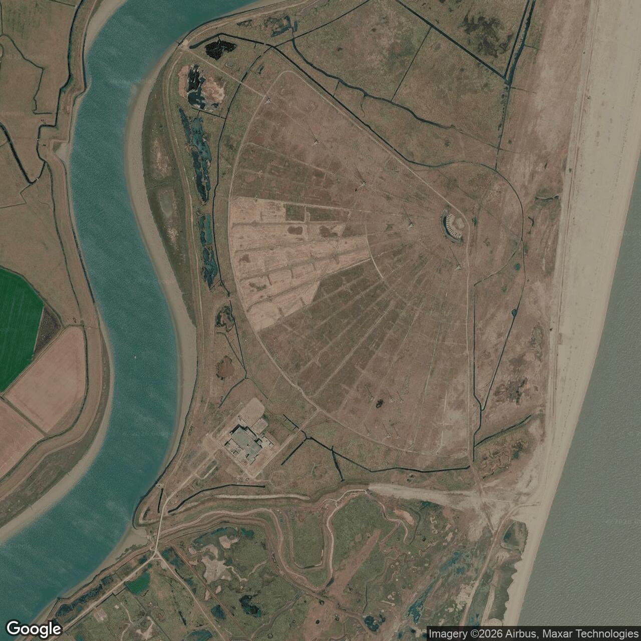
Historical photographs and drawings
The declassified MITRE study reproduces a U.S. Air Force aerial of the array, an antenna-string photograph, engineering diagrams, and test displays. These are the visual controls for the accompanying graphic. Modern views of the surviving building show its later broadcast reuse, not an intact AN/FPS-95 radar.
Information sources (21)
- PDFFowle, Key, Millar, and Sear, The Enigma of the AN/FPS-95 OTH Radar, complete declassified technical paper
Detailed firsthand system description, performance record, noise investigation, competing hypotheses, conclusions, figures, and source bibliography
- PDFUnited States Air Force historical extracts, System 441A
Program chronology, mission, RCA contract, antenna incidents, acceptance, DVST and IOT&E, Scientific Assessment Committee, and termination decision
- WEBNational Trust, History of Orford Ness
Official site history for military research use, later clearance activity, transfer to the National Trust, protected shingle landscape, and visitor context
- WEBSuffolk Heritage Explorer, ORF 177 Cobra Mist
County historic-environment record for the radar, approximate site center, array description, later broadcasting use, and private ownership
- WEBHistoric England, Atomic Weapons Research Establishment Orford Ness Survey Report landing page
Government heritage-research record for the wider Cold War landscape, including Cobra Mist construction, fitting-out, testing, failure, and reuse context
- WEBHistoric England, Orford Ness scheduled monument list entry 1416933
Official heritage description of the wider research landscape, surviving structures, physical setting, and protected areas distinct from the Cobra Mist property
- WEBIRGON, Cobra Mist
Specialist Orford Ness research summary with period imagery, coverage diagram, array layout, code-name evolution, calibration, final transmission, and source notes
- PDFD. J. Emery, The Cobra Mist Test Antennas
Documented construction, dimensions, location, purpose, and remnants of the 23.145-megahertz comparative Yagi and other special test antennas
- PDFIRGON, Orfordness Power Networks
Research synthesis of mainland supply, submarine cables, Cobra Mist substations, later BBC reuse, and the surviving electrical network
- WEBD. B. Trizna, AN/FPS-95 Research and Development Program, Long-Path One-Way Propagation Effects
Naval Research Laboratory final technical report on reciprocal path testing, ionospheric dynamic range, transmitter purity, antenna comparison, and measurement limits
- WEBNaval Research Laboratory, AN/FPS-95 near-range phenomena report
Technical evidence on meteor-trail reflections, surface-wave clutter spreading, antenna vibration, and limits of local noise explanations
- WEBNaval Research Laboratory Report 7752, AN/FPS-95 System
Declassified technical report with system description, parameters, and research-program evidence
- PDFGovernment Attic, DTIC Technical Report Bibliography for Repeater, 1942-1974
Bibliographic control for AN/FPS-95 final reports, report numbers, dates, contractors, distribution histories, and later declassification status
- WEBCUFON, FOIA Documents on Cobra Mist, Part 1
Transcription and presentation of declassified Air Force and technical records used as a discovery aid where original agency downloads are unavailable
- WEBCUFON, FOIA Documents on Cobra Mist, Part 4
Reference list and concluding pages from the declassified technical paper, including ESD-TR-73-270 component reports and committee records
- WEBUK Companies House, Cobra Mist Limited
Current official corporate status, incorporation date, registered office, and telecommunications business classification
- PDFPlanning Inspectorate, Norfolk Projects Lesser Black-Backed Gull Implementation and Monitoring Plan
Current government planning record documenting Cobra Mist Limited land interest, lease dates, ecological use, and modern property context
- WEBWikimedia Commons, Orfordness Transmitting Station category
Modern overview collection of the surviving former Cobra Mist building, later BBC antennas, surrounding landscape, and access context
- WEBWikimedia Commons, former Cobra Mist building photograph
Recent geolocated view of the surviving main building for architectural comparison, not evidence of original radar internals
- WEBWikimedia Commons, Cobra Mist masts at Orford Ness
2007 photograph described as dismantled radar masts; identification should remain qualified unless matched to original mast drawings
- WEBWikimedia Commons, Orford Ness transmitting station Cobra Mist site
Wide modern view of the former radar building and later transmitting landscape for present-condition comparison