
AN/FPS-23 Fluttar Radar
The fixed UHF radio fence that watched low-altitude gaps in the original DEW Line, and the engineering and operational problems that ended its six-year service.
Designation and Identity
The AN/FPS-23 was one of the strangest radars ever placed into a continental air-defense network. It did not rotate, did not paint a normal plan-position display, and did not measure the range and azimuth of an aircraft in the way a conventional search radar did. Instead, it created a continuous radio-frequency fence between geographically separated transmitter and receiver stations. An aircraft crossing that fence altered the received signal through the Doppler effect, producing an alarm that told Distant Early Warning Line personnel that something had crossed a low-altitude gap between the larger search radars. Air Defense Command described the equipment simply and accurately as a "Doppler type radar (DEW)." [1]
The production system was widely known as Fluttar, a contraction of "flutter radar" that originated during MIT Lincoln Laboratory development. The nickname is more informative than the formal designation because it points toward the system's defining principle. The AN/FPS-23 watched for a moving target's modulation of a steady continuous-wave field rather than waiting for reflected pulses and calculating range from elapsed time. The system was consequently closer to an electronic tripwire than to the rotating AN/FPS-19 that formed the main search backbone of the DEW Line. It answered a very specific question: had a sufficiently fast aircraft crossed this fence at low altitude? [1] [3]
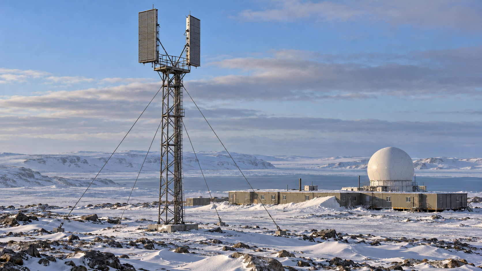
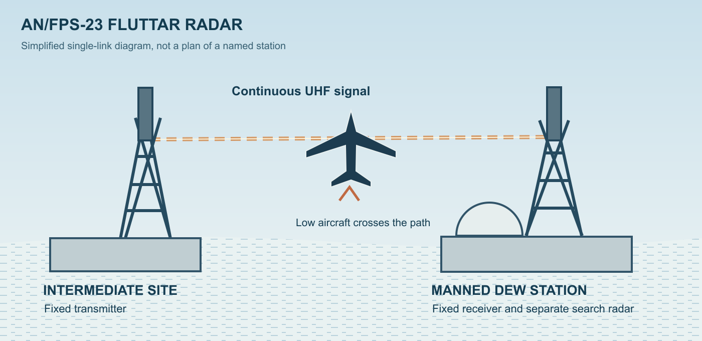
The AN/FPS-23 designation also described a distributed system rather than one self-contained cabinet or radar van. Production DEW Line installations used AN/FPT-4 Fluttar transmitters at Intermediate sites and AN/FPR-2 Fluttar receivers at neighboring Main and Auxiliary sites. A transmitter and receiver were normally separated by roughly fifty miles. One Intermediate station could support eastward and westward links, while receivers at the larger stations watched the corresponding paths. The equipment must therefore be understood as a geographically extended radar system whose functional components could be dozens of miles apart. Treating "AN/FPS-23" as a single monostatic radar set obscures the central engineering feature that made Fluttar distinctive. [1] [5] [6]
Development Origins and Contractor Roles
The requirement for Fluttar grew from the same strategic problem that produced the DEW Line itself. By the early 1950s the United States and Canada feared that Soviet long-range bombers could approach across the Arctic and reach North American targets before existing radar networks provided adequate warning. MIT Lincoln Laboratory's northern warning studies helped establish the case for placing radar far above the populated areas of Canada and the United States. The system had to operate across enormous distances, under extreme weather conditions, and with far smaller technical staffs than conventional continental radar stations. The search radar that became AN/FPS-19 addressed much of that requirement, but Earth curvature and local terrain left a low-altitude vulnerability between widely spaced stations. [1] [3]
The Canadian Mid-Canada Line showed that separated transmitters and receivers could create a radio fence. An aircraft crossing the path produced a strong forward-scatter response without ordinary range measurement. Lincoln Laboratory researchers examined that approach for the DEW Line but expected serious bird-alarm problems. They developed a different antenna orientation and Doppler processing to discriminate faster aircraft from much slower moving targets. [3]
Lincoln Laboratory developed its bistatic continuous-wave gap-filler under the nickname Fluttar. Its 1955 prototype operated at approximately 408 MHz, and Motorola built a large transmitter to Lincoln Laboratory specifications. The fielded AN/FPS-23 later operated from 475 to 525 MHz. [3] [4]
MIT Lincoln Laboratory was the principal development organization for the Fluttar concept, signal-processing approach, and prototype equipment. Motorola manufactured the production radar hardware identified in Air Force historical material and specialist DEW Line technical records. Western Electric had the much broader systems-integration, engineering, procurement, construction, and installation responsibility for the DEW Line. Its role included turning laboratory concepts and production electronic equipment into an operating chain of Arctic sites with towers, buildings, power, communications, spares, transportation, and maintenance support. Bell Telephone Laboratories later worked on an improved Doppler Spectrum Analyser intended to make the FPS-23's difficult graphic output easier for operators to interpret. [1]
Why the DEW Line Needed a Doppler Fence
The AN/FPS-19 could survey a large volume of Arctic airspace, but it was still a line-of-sight radar. Earth curvature and terrain meant that a low-flying aircraft might remain below the search radar horizon until it was relatively close to a station. Technical histories describe the gap between neighboring DEW search radars as potentially allowing undetected flight below roughly 2,000 feet over favorable nonreflecting terrain and as high as roughly 4,000 feet in less favorable reflecting conditions. ADC's official DEW Line history expressed the operational concern more broadly, warning that targets flying especially below about 5,000 feet could conceivably slip through low-altitude coverage gaps. [1] [3]
The FPS-23 was not designed to extend the normal range of the AN/FPS-19. It was designed to close the space between search radars at the bottom of the coverage volume. A typical transmitter-receiver spacing of about fifty miles created a baseline across which a low aircraft had to pass. The system's stated design criterion was detection at altitudes down to approximately 200 feet over land and 50 feet over water. Those are low-altitude design criteria, not a published altitude ceiling. The AN/FPS-23 did not attempt to provide three-dimensional tracking over a broad airspace volume. It existed to create a narrow warning fence in the region where ordinary line-of-sight search coverage was weakest. [1] [3]
The often quoted distance of about fifty miles described the usual separation between a transmitter and receiver. It was the length of a bistatic fence segment, rather than the instrumented range of a rotating radar. A crossing aircraft produced a Doppler signature, but the system did not return a conventional slant-range measurement that could be plotted like an AN/FPS-19 target. [1] [3]
Intermediate transmitter sites were much smaller than the radar stations on either side. The standard five-module train accommodated a four-to-five-person crew, compared with roughly sixteen to eighteen civilians at an Auxiliary site. Even that small crew required power, heat, fuel, water, food, shelter, transport, and communications. Across twenty-eight Intermediate locations, the fixed Doppler fence therefore imposed a substantial operating and resupply burden. [1] [5] [6]
Technical Specifications
The production AN/FPS-23 operated between 475 and 525 MHz in the UHF band and transmitted one kilowatt of continuous radio-frequency power. Because Fluttar sent a continuous signal rather than pulses, pulse width and pulse-repetition frequency did not apply. Its one-kilowatt output was continuous power, with no peak-to-average pulse conversion. [1] [3]
Air Defense Command described a fixed transmitting antenna about 20 feet high and six feet wide, mounted 100 to 400 feet above ground according to terrain. Its receiving antenna was similarly large and elevated. Tower height varied with the clearance needed along each transmitter-to-receiver path. [1]
The antennas did not rotate. Fluttar established fixed east-west or adjacent-site paths. Intermediate sites carried transmitting equipment directed toward receivers at neighboring stations, while Main and Auxiliary sites carried receivers for the corresponding links. Lincoln Laboratory technical history describes the antenna pattern work as including angular displacement and filtering designed to reduce bird responses. A later Naka and Ward account describes a cosecant-squared horizontal pattern designed by Leon Ricardi and shows a representative Baffin Island installation with two fixed receiving antennas on a tall tower, each directed toward a neighboring transmitter site. The unusual antenna geometry was fundamental because the system's job was to shape a fence rather than sweep 360 degrees. [1] [3]
The system filtered out targets moving below about 125 miles per hour in an effort to reduce alarms caused by migratory birds. False alarms nevertheless remained severe. Birds, light aircraft, unusual propagation, weather, power changes and interference could still trigger warnings, making the speed threshold an incomplete solution. [1] [3]
How the Bistatic Doppler System Worked
The physics of the AN/FPS-23 was simple in concept. A transmitter radiated a steady radio-frequency field toward a distant receiving station. In an empty path, the receiver saw a relatively stable signal. When an aircraft crossed the field, the moving target scattered and modulated some of that energy. Relative motion produced Doppler frequency components that differed from the steady carrier and from much of the stationary background. Filters could then pass frequency components associated with aircraft-like motion and use them to trigger an alarm. [1] [3]
This was a bistatic geometry because the transmitter and receiver occupied different places. In a conventional monostatic pulse radar, the same site sends a pulse toward the target and listens for the echo, using time delay to measure range. In Fluttar, the long transmitter-to-receiver baseline was itself the sensing geometry. The most important operational event was the target's passage through the electronic fence. The system could indicate that a crossing had occurred and provide signal characteristics useful to the operator, but it did not independently create the normal range-azimuth track expected from a rotating search radar. [1] [3]
The production system used AN/FPT-4 transmitters at Intermediate sites and AN/FPR-2 receivers at Main and Auxiliary sites. Specialist DEW technical documentation describes the Intermediate equipment module as containing four AN/FPT-4 transmitters, two primary units and two standby units. A typical station therefore maintained redundancy for eastward and westward fence segments. The paired receiving stations monitored the paths from opposite sides. This architecture meant that one physical Intermediate site was only part of multiple AN/FPS-23 links. It also explains why a simple count of "radars" can differ from a count of sites, transmitters, receivers, or fence segments. [1] [5] [6]
The receiver's signal processing had to separate a meaningful aircraft signature from the enormous variety of natural and technical disturbances that occurred in an Arctic radio path. DEW specialist documentation describes a dual-feed antenna system feeding audio filters that passed frequencies corresponding to aircraft Doppler signatures. Target information could be recorded on magnetic tape and displayed on a strip recorder for operator analysis. ADC's official history describes the graphic display as pen recordings on electrographic paper and judged the original presentation barely readable. This was a warning system that demanded interpretation of traces and alarms, not a familiar rotating sweep with a clean target blip. [1] [3]
The AN/FPT-4 Transmitter and AN/FPR-2 Receiver Network
The AN/FPT-4 and AN/FPR-2 designations are essential to understanding the production system. The AN/FPT-4 was the Fluttar transmitter used at Intermediate sites. The AN/FPR-2 was the receiver at Main and Auxiliary sites. Contemporary memories and specialist technical descriptions repeatedly identify this pairing. The higher-level AN/FPS-23 designation described the operational radar function created when those geographically separated components worked together. [1] [5] [6]
The Intermediate sites were deliberately small. A documented standard layout used five linked modules, each about 28 feet wide, 16 feet long, and 10 feet high, for a train about eighty feet long. The first module held three 20-kW generator sets; the second contained four AN/FPT-4 transmitter positions, two primary and two standby, with a GE VO-38 VHF radio. The remaining modules provided kitchen and dining space, sleeping space, a 400-cycle motor-generator for transmitter power, water, fuel, and storage. The firsthand FOX-A account records a local variation with two generators in the power module and a third standby generator in the garage. The layout and power arrangement varied by station. [6] [7]
The receiving end was housed at the much larger Main and Auxiliary stations. Auxiliary stations typically used about twenty-five linked modules, including an electronics area for radar, communications, maintenance, and operations. A firsthand account from FOX-A identifies the operational receiver at the adjacent station as the AN/FPR-2. The receiving equipment was thus part of a staffed search-radar installation. [1] [6] [7]
At Main sites the receiving function was part of an even larger command and communications plant. ADC's history says each Main station combined an AN/FPS-19 search set with an FPS-23 Fluttar receiver and extensive communications. Main sites were the sector focal points where track reports, communications, administration, maintenance, and command functions were concentrated. The FPS-23 receiver at such a station was therefore only one element in a much larger surveillance chain. When it alarmed, the operator had to determine whether the crossing was meaningful and pass information into the lateral and rearward reporting system. [1] [5]
Power, Towers, Modules, and Arctic Support
The AN/FPS-23 could not be separated from its Arctic support plant. ADC historical material states that both the FPS-19 and FPS-23 systems were powered by nearby banks of diesel generators. Intermediate stations existed specifically because a transmitter had to be positioned between larger stations, which meant building a functioning settlement around a radio-frequency requirement. Even a four-to-five-person location needed heat, fuel, food, water, shelter, emergency communications, a landing strip or other resupply access, spare parts, tools, fire protection, and vehicles capable of operating in extreme cold. [1]
The tower was one of the most visible FPS-23 features. Height varied from roughly 100 to 400 feet according to terrain because the line-of-sight path to the neighboring station had to remain clear. A tower hundreds of feet tall on Arctic tundra was not a trivial accessory. It had to withstand severe winds, icing, low temperatures, and difficult foundation conditions. Construction equipment, concrete or anchoring systems, tower sections, feed lines, antennas, and climbing hardware all had to be moved to sites that often had no road connection to the outside world. [1] [6]
The short Intermediate module train reveals the austere personnel concept. Five modules were dramatically smaller than a Main or Auxiliary station, but the people assigned there still lived through an Arctic winter. Firsthand accounts describe the isolation more vividly than engineering plans. FOX-A photographs show the Doppler tower, the module train, the airstrip environment, local heavy equipment, and the low horizon that made the site appear almost featureless from the air. The radar mission may have been narrow, but maintaining that mission demanded personnel who could handle electronics, generators, vehicles, weather, runway support, and ordinary daily survival. [1] [5] [6]
Operators, Crew, and Training
Air Defense Command authorized approximately 45 to 50 civilian staff and six officers at each Main station, sixteen to eighteen civilians at a typical Auxiliary station, and four to five people at an Intermediate station. Federal Electric Company personnel operated and maintained much of the line under military oversight. The Intermediate crews included the technicians and support personnel needed to keep a transmitter, generators, shelter, communications, and local transport working through the Arctic winter. [1]
Training was centralized before personnel moved north. The DEW training facility near Streator, Illinois, used representative electronic equipment and a curriculum that combined radar, communications, weather, Arctic survival, and operations. A remembered 1960-1961 Radician syllabus placed AN/FPS-19 theory and practical work in weeks seven and eight and AN/FPS-23 Doppler radar theory and practical work in week nine. Students then moved into operations and communications subjects. This sequence shows that Fluttar was treated as an integral surveillance discipline rather than a minor add-on that could be learned casually after arrival. [1] [8]
Project Red Sea nevertheless concluded that personnel training and operating practices required improvement. The problem was not simply whether technicians understood a schematic. Operators confronted a system that produced frequent nuisance alarms and a difficult graphic output. Confidence in the equipment eroded when alarms repeatedly proved false. That human factor was operationally dangerous because a legitimate target could be ignored after personnel became conditioned to expect another false indication. Radar reliability and human attention therefore interacted. The worse the alarm quality became, the less useful even a technically valid detection could be. [1]
The Alarm System and Doppler Spectrum Analyser
Automatic alarm was central to the DEW concept because planners did not want operators staring continuously at every display across thousands of miles of warning line. The FPS-23 was intended to produce an immediate indication when an aircraft crossed the fence. Its alarm processing looked for Doppler signatures corresponding to aircraft-like motion and rejected or attenuated lower-speed phenomena. In theory this reduced manpower while increasing the chance that a brief crossing would not be missed. [1] [3]
In practice, the original alarm and display combination was one of the radar's greatest weaknesses. ADC's history describes false alarms caused by weather, unusual propagation, power-supply variations, electronic disturbances from adjacent transmitters, and other effects. Western Electric technicians reduced some transmitter-interference problems in 1958 by changing antenna angles, but there was no simple correction for the full range of nuisance responses. The system could produce as many as four false alarms per minute under some conditions. [1]
The original graphic display recorded target information as pen traces on electrographic paper. Air Defense Command judged the result barely readable. Bell Laboratories developed the Doppler Spectrum Analyser, or DSA, to make an aircraft crossing easier to follow on the display. ADC endorsed the change by the end of 1958, but anticipated a long production and installation schedule. [1]
Project Red Sea, 1958
Project Red Sea, conducted from May 1 through September 2, 1958, provided the clearest early operational test of the completed DEW Line. Thirteen Main, Auxiliary, and Intermediate sites between Cambridge Bay and Hall Beach took part. Twelve Strategic Air Command B-52 and KC-97 aircraft made seventy-three separate penetrations at altitudes from roughly 2,000 to 45,000 feet. The AN/FPS-19 search chain detected every flight. Seventy-two were reported rearward, and seventy-one of those reports reached controllers at NORAD or the Royal Canadian Air Force. That strong search-radar result made the weaker FPS-23 performance especially visible. [1]
The FPS-23 produced a very different result. ADC's official study says only 79 percent of forty-nine known penetrations of the Doppler system were actually detected, and not all detected events were relayed laterally to Main station controllers. The alarm system generated more false alarms than real alarms. This was not a minor shortfall in a radar meant to serve as an automatic low-altitude tripwire. The network's value depended on a high probability that a brief crossing would be detected and acted upon. Missing roughly one penetration in five while simultaneously flooding operators with false alarms undermined confidence in the entire concept. [1]
The test also exposed organizational problems. Some radar targets elsewhere in the system went unreported because console operators failed to pass them, although overlapping FPS-19 coverage prevented those omissions from changing the final test result. Training at Streator and on the job was criticized. The Air Force and contractors therefore had to improve not only electronics but reporting discipline, training, supervision, and maintenance. Red Sea showed that a warning line could be technically impressive yet still fail if the human and communications chain did not treat detections consistently. [1] [8]
For Fluttar, the response was an intensive corrective effort. Engineers investigated the false-alarm sources, Western Electric adjusted antenna angles to reduce interference from nearby transmitters, Bell Laboratories developed the DSA, and Federal Electric training and management received increased scrutiny. These efforts kept the radar in service for several more years, but they did not transform it into a highly trusted sensor. The Red Sea numbers remained an important warning that the low-altitude fence was the weakest electronic part of the original DEW system. [1]
Birds, Light Aircraft, and False Alarms
Fluttar's design lineage was strongly influenced by the failure of earlier radio fences to distinguish military aircraft from migrating birds. The AN/FPS-23 therefore used Doppler filtering and a low-speed rejection criterion intended to ignore movement below roughly 125 miles per hour. This was a clever response to one of the most obvious problems of the Mid-Canada Line approach. A Soviet bomber should cross the fence much faster than a flock of birds, so velocity discrimination appeared to offer an economical method of reducing nuisance alarms. [1] [3]
Operational reality was less cooperative. Birds still produced false alarms, and bush aircraft or DEW Line support flights were especially difficult to distinguish from intruders because they were real aircraft crossing the same paths. The warning network depended on such flights for personnel movement, mail, supplies, inspection, and emergency support. The radar had to operate in an environment where authorized traffic could trigger the same crossing alarm as a threat. [1] [3]
The resulting nuisance alarms created a human reliability problem more serious than the raw false-alarm count. An alarm that is wrong once may attract careful investigation. An alarm that is wrong several times a minute can train the operator to dismiss it. ADC explicitly worried that Federal Electric personnel were losing confidence in the FPS-23's aural and visual warnings. A true crossing could therefore be electronically detected but operationally lost because the human system had learned that Fluttar alarms were usually meaningless. [1] [3]
This distinction is central to the radar's legacy. AN/FPS-23 was not simply a piece of hardware that "did not work." It demonstrated that an automatic warning device has to be judged by the complete decision chain from physical detection to operator interpretation to reporting. A radar can have enough sensitivity to respond to targets yet still be operationally poor if false alarms dominate, displays are unclear, and the operator cannot distinguish a threat from routine traffic. Fluttar became an early Cold War example of the modern signal-detection tradeoff between probability of detection and false-alarm rate. [1] [3]
1961-1962 Evaluations and the Changing Threat
Project High Look in 1961 tested the AN/FPS-19 search radar at high altitude and recorded detections approaching 200,000 feet. It did not resolve the AN/FPS-23's low-altitude difficulties. Air Defense Command continued to weigh the Doppler fence's contribution against its cost, maintenance burden, and persistent false alarms. [1]
A 1962 ADC operational readiness inspection of the FOX and DYE sectors again criticized the Doppler system. The inspection found that five faker-aircraft penetrations and a number of friendly-aircraft penetrations did not register even though performance readings indicated the radars were operating within acceptable standards. One low-level faker specifically testing the FPS-23 escaped detection. This was particularly damaging evidence because it suggested the problem could persist even when maintenance measurements said the equipment was technically within limits. [1]
At the same time, the strategic context changed rapidly. Intercontinental ballistic missiles were emerging as the dominant immediate threat to North America. A radar fence optimized to detect low-flying bombers crossing the Arctic could not provide warning of ballistic missiles traveling on an entirely different trajectory and at vastly greater speed and altitude. NORAD therefore reconsidered how much money and manpower should be spent maintaining the lowest-altitude DEW requirement. [1]
In 1962 NORAD offered to raise the DEW Line low-altitude requirement to 5,000 feet. ADC welcomed the change because it opened a path to remove the FPS-23 network. In November 1962 ADC told the Air Force that the radar had demonstrated virtually no operational usefulness and urged that its operation be discontinued as soon as possible. The wording was unusually severe for an official command history and reflected years of frustration rather than one isolated test failure. [1]
Retirement in 1963
The Air Force ordered the twenty-eight FPS-23 Intermediate sites inactivated in July 1963. Twenty were in Canada and eight were in Alaska. The effective date was 1963-07-21. ADC's history says the number of sites along the DEW Line proper was thereby reduced from fifty-seven to twenty-nine. The reduction was possible because the Intermediate stations existed principally for the Fluttar transmitting mission. Once the low-altitude fence was abandoned, those tiny sites no longer had a principal operational purpose. [1]
After Fluttar closed, Air Defense Command readjusted the AN/FPS-19 to improve its low-altitude coverage within the revised requirement. U.S. officials also negotiated with Canada over closing the Intermediate stations on Canadian soil. The remaining Main and Auxiliary stations continued their search-radar and communications missions. [1]
The 1963 decision also showed how quickly a major Cold War program could become expendable when doctrine changed. Only six years separated the DEW Line's 1957 operational opening from the FPS-23 network's removal. The radar had been conceived during a period when low-flying Soviet bombers dominated the planning problem. By 1963 ballistic missiles were reshaping warning priorities, and a troublesome low-altitude fence no longer commanded the same strategic urgency. Fluttar therefore had a short operational life even though the DEW Line itself continued for decades. [1]
Deployment Across the DEW Line
The deployment pattern was not universal. The Greenland extension used AN/FPS-30 Sentinel radars rather than extending the same FPS-23 fence architecture across the rugged DYE extension. The Aleutian extension also relied on conventional search radars without a chain of Fluttar Intermediate sites. ADC historical analysis explains that terrain in these extensions reduced the concern that an attacker could exploit the same low-altitude corridor geometry. This negative evidence is important because it shows that AN/FPS-23 was a mission-specific solution, not a standard accessory automatically issued with every DEW radar. [1]
Main, Auxiliary, and Intermediate Site Roles
The DEW Line station hierarchy explains where the AN/FPS-23 was installed. Main stations were regional hubs with the principal search radar, sector control and reporting functions, communications, maintenance facilities, and large crews. Air Defense Command identified six Main stations on the original line: Point Barrow, Barter Island, Cape Parry, Cambridge Bay, Hall Beach, and Cape Dyer. Each had an FPS-23 receiving installation alongside its other radar equipment. [1]
Auxiliary stations sat between Main locations at roughly hundred-mile intervals and carried their own AN/FPS-19 search radars plus FPS-23 receiving equipment. ADC's formative plan counted twenty-three Auxiliary stations, with roughly sixteen to eighteen civilians assigned to a typical location. Their job was to detect aircraft, report tracks to Main stations, sustain communications, and maintain local systems. An Auxiliary station was therefore a full radar station, not merely the far end of a Fluttar link. [1]
Intermediate sites were the specialized AN/FPS-23 transmitter locations. They were placed between the larger radar sites so the continuous-wave paths could form low-altitude fences. ADC counted twenty-eight of them and described each as a four-to-five-man station equipped solely with the FPS-23 Fluttar transmitting function and lateral voice communications by FM mobile radio. The specialist equipment description refines that wording by identifying four AN/FPT-4 transmitter units, local power conversion, and redundant east-west transmission arrangements. [1] [5] [6]
This three-level architecture explains the 1963 reduction from fifty-seven to twenty-nine sites. Removing the twenty-eight Intermediate locations did not eliminate the Main and Auxiliary search-radar chain. It removed the special transmitter sites that existed to make the Doppler fence continuous. The receiving equipment at surviving stations could then be removed while the rest of each station continued. The DEW Line became a simpler network centered on the conventional search mission and improved operating procedures rather than the original dual-radar architecture. [1]
Operational Support and Communications
An FPS-23 alarm had value only if the warning could move through the DEW reporting system. Intermediate stations used local VHF communications to maintain contact with neighboring larger stations and with aircraft bringing personnel and supplies. Main and Auxiliary stations were tied together by lateral communications systems such as the AN/FRC-45 UHF troposcatter network and by rearward communications that carried surveillance information south to command centers. The radar fence was therefore one sensor layer inside a communications architecture spanning the Arctic and the continental defense system. [1] [6]
ADC's history repeatedly emphasizes that communications reliability could be as important as radar detection. Early DEW rearward circuits suffered garbling and inconsistent procedures. During Project Red Sea, lateral circuits performed well when operators used them correctly, but some FPS-23 detections were not relayed. A perfect electronic alarm at an Intermediate or receiving station could not defend North America if it failed to reach a controller empowered to act. [1]
The reporting chain also had to coexist with normal Arctic aviation. Scandinavian Airlines and other civil flights crossed northern warning zones, while DEW support aircraft moved laterally between sites. Identification procedures, flight plans, communications, and military reporting rules were intended to prevent every legitimate aircraft from escalating into a national alert. Fluttar complicated this environment because it produced a crossing alarm without the same range-azimuth track quality a conventional search radar could provide. Operators often needed information from other sensors and communications channels to understand what the alarm meant. [1] [6]
The radar's operational value was therefore inseparable from the AN/FPS-19 and the human control network. The FPS-23 was not an independent air-defense station. It was a cueing layer. Its ideal contribution was to warn that a low target had crossed where primary search coverage was weak, allowing other sensors, communications, and control centers to investigate. The more often that cue proved false, the less useful the entire layer became. [1] [6]
Training, Maintenance, and Life at the Intermediate Sites
The people who kept Fluttar operating lived in conditions very different from those of a conventional U.S. radar base. Intermediate sites could be hundreds of miles from meaningful road networks and depended on aircraft, seasonal sealift, or difficult overland movement for supplies. A failure of a generator, heater, radio, or transmitter could threaten not merely the surveillance mission but the safety of the entire small crew. Radicians therefore needed broad practical competence and could not treat electronics as an isolated specialty. [6] [7]
The Streator training program covered weather, survival, communications, FPS-19 operation, FPS-23 theory and practical maintenance, first aid, and reporting procedures. A specialist history estimates that approximately 150 students passed through the facility each year. Formal technical preparation helped new personnel maintain radar equipment sooner after reaching northern stations. [1] [8]
Modifications and Nomenclature
Lincoln Laboratory's approximately 408 MHz prototype preceded the production AN/FPS-23 operating band of 475 to 525 MHz. The frequency change was part of the system's transition from laboratory development to the fielded DEW Line installation. [3] [4]
The Doppler Spectrum Analyser was a modification effort. Bell Laboratories designed it after crews found the original pen-recording display difficult to read. Air Defense Command endorsed it by the end of 1958, but anticipated manufacture, delivery, and installation to take at least another twenty months. [1]
Antenna-angle adjustments in 1958 represent another field correction. Western Electric technicians found that some false alarms originated in electronic interference from adjacent transmitters and reduced that problem by readjusting antenna angles. This did not eliminate weather, propagation, power, traffic, or other false-alarm sources. It illustrates the kind of operational engineering that occurs when a theoretically clean bistatic geometry meets a real network of multiple nearby transmitters, variable terrain, and changing propagation conditions. [1]
Other Radar Systems and the Later Warning Network
The AN/FPS-23 did not replace the AN/FPS-19. It complemented it. The FPS-19 remained the principal search radar at Main and Auxiliary locations, providing broad azimuth and range surveillance. Fluttar occupied the low-altitude gaps between those search stations. The two systems therefore formed layers of one warning architecture, with communications and operator procedures linking their reports. [1] [3]
The closest conceptual predecessor was not a single U.S. radar designation but the Canadian Mid-Canada Line forward-scatter fence and Lincoln Laboratory's own developmental Fluttar equipment. Those systems demonstrated that separated transmitters and receivers could create an economical warning barrier. The AN/FPS-23 altered the concept with Doppler discrimination and other techniques intended to reduce bird alarms and adapt the fence to DEW requirements. [1] [3]
There was no one-for-one equipment successor installed at every FPS-23 location after 1963. The Air Force removed the Intermediate sites rather than replacing each with a newer Doppler radar. NORAD relaxed the low-altitude requirement, ADC adjusted and relied more heavily on the FPS-19, and the surviving DEW sites continued the strategic warning mission without a comparable continuous chain of Intermediate transmitters. [1] [3]
Decades later, the North Warning System fielded AN/FPS-117 long-range and AN/FPS-124 short-range radars. These scanning radars belonged to a different sensor architecture from the fixed Fluttar fence. [9]
Technical Summary
- Designation
- AN/FPS-23, Fluttar or Flutter radar
- Role
- Low-altitude gap-filling aircraft alarm on the original DEW Line
- Operating principle
- Fixed, bistatic continuous-wave Doppler fence
- Production manufacturer
- Motorola
- Frequency
- 475 to 525 MHz, UHF
- Transmitted power
- 1 kW continuous wave
- Typical transmitter-receiver separation
- About 50 miles
- Antenna
- Fixed directional panels about 20 feet high by six feet wide, mounted 100 to 400 feet above ground depending on terrain
- Original network
- Twenty-eight dedicated Intermediate sites plus receiving equipment at Main and Auxiliary stations
- Intermediate-site closure
- July 21, 1963
Chronology
- 1952: MIT Lincoln Laboratory northern air-defense studies help define the need for an Arctic warning barrier. [1] [2]
- 1955: Lincoln Laboratory develops its continuous-wave Fluttar prototype; prototype documentation records approximately 408 MHz. [3] [4]
- 1956: Construction and electronic installation of the original DEW Line accelerate across Alaska and Canada. [1]
- 1957: The production AN/FPS-23 enters service with the original DEW Line. [1]
- 1958: Project Red Sea finds that the FPS-23 detects 79 percent of 49 known fence crossings and produces more false alarms than genuine alarms. [1]
- 1958: Western Electric changes some antenna angles to reduce transmitter interference; Bell Laboratories develops the Doppler Spectrum Analyser. [1]
- 1959: Federal Electric revises training and supervision after criticism of operating practices. [1]
- 1961: Project High Look examines the primary search-radar coverage that affects the need for a separate Doppler fence. [1]
- 1962: A readiness inspection reports missed low-level crossings in the FOX and DYE sectors. [1]
- November 1962: Air Defense Command recommends discontinuing AN/FPS-23 operation. [1]
- July 21, 1963: The Air Force inactivates all 28 dedicated AN/FPS-23 Intermediate stations. [1]
- 1980s: The North Warning System fields a new generation of northern surveillance radars, including the AN/FPS-117 and AN/FPS-124. [9]
Related Sites
Information sources (9)
- PDFThomas W. Ray, Air Defense Command Historical Study No. 31, A History of the DEW Line, 1946-1964
Primary Air Defense Command history supporting the FPS-23 technical description, site architecture, personnel, Project Red Sea performance, false-alarm history, DSA program, 1962 evaluation, and 1963 inactivation.
- WEBMIT Lincoln Laboratory, SAGE and Early Air Defense History
Official laboratory historical overview supporting Lincoln Laboratory's role in early continental air-defense technology and the development of bistatic continuous-wave gap-filler radar that became AN/FPS-23.
- PDFF. Robert Naka and William W. Ward, Distant-Early-Warning Line Radars: The Quest for Automatic Signal Detection
Lincoln Laboratory Journal technical history supporting Fluttar development, radar-fence geometry, antenna-pattern development, automatic detection, false alarms, and the historical statement that sixty Flutter radars were deployed.
- PDFJohn W. Delaney et al., Widgets and Wonders: Lincoln Laboratory's Unique Radar Hardware Legacy
Lincoln Laboratory Journal source documenting the 408 MHz prototype Fluttar, Motorola transmitter built to Laboratory specification, receiver, and prototype antenna photographs.
- WEBDEWLine Adventures, Technical Info
Specialist technical source supporting production 475-525 MHz operation, 1 kW continuous-wave output, AN/FPT-4 transmitter and AN/FPR-2 receiver component designations, approximate fifty-mile spacing, and representative signal-processing descriptions.
- WEBThe DEWLine, Auxiliary and Intermediate Site Layouts
Specialist site-layout source supporting five-module Intermediate stations, generator arrangements, four AN/FPT-4 transmitter positions, 400-cycle power conversion, tower heights, and four-to-five-person staffing recollections.
- WEBThe DEWLine, FOX-A Bray Island
Firsthand site recollection and photographs supporting a representative Intermediate station layout, AN/FPT-4 and AN/FPR-2 system relationship, power configuration, staffing, tower, and Arctic operating environment.
- WEBThe DEWLine, Streator Illinois Training Site
Specialist training-history source supporting Federal Electric DEW technician training and a remembered syllabus that included AN/FPS-23 theory and practical instruction in week nine.
- WEBHill Air Force Base, Unit at Hill AFB Sustains Radars, Bolsters Nation's Homeland Defense, 2020
Air Force source for the later North Warning System and its AN/FPS-117 long-range and AN/FPS-124 short-range radars.