
AN/FPS-3 Early-Warning Search Radar
- Role
- Fixed, two-dimensional, long-range aircraft-search radar
- Manufacturer
- Bendix Radio Division; early antenna contract held by Airborne Instruments Laboratory
- Frequency
- 1220 to 1365 MHz, per MIL-HDBK-162A
- Network service
- Early 1950s through July 1964 in the Air Defense Command basic FPS-3 inventory
- Altitude information
- Provided by a separate height finder, not the FPS-3 search set
Identity and significance
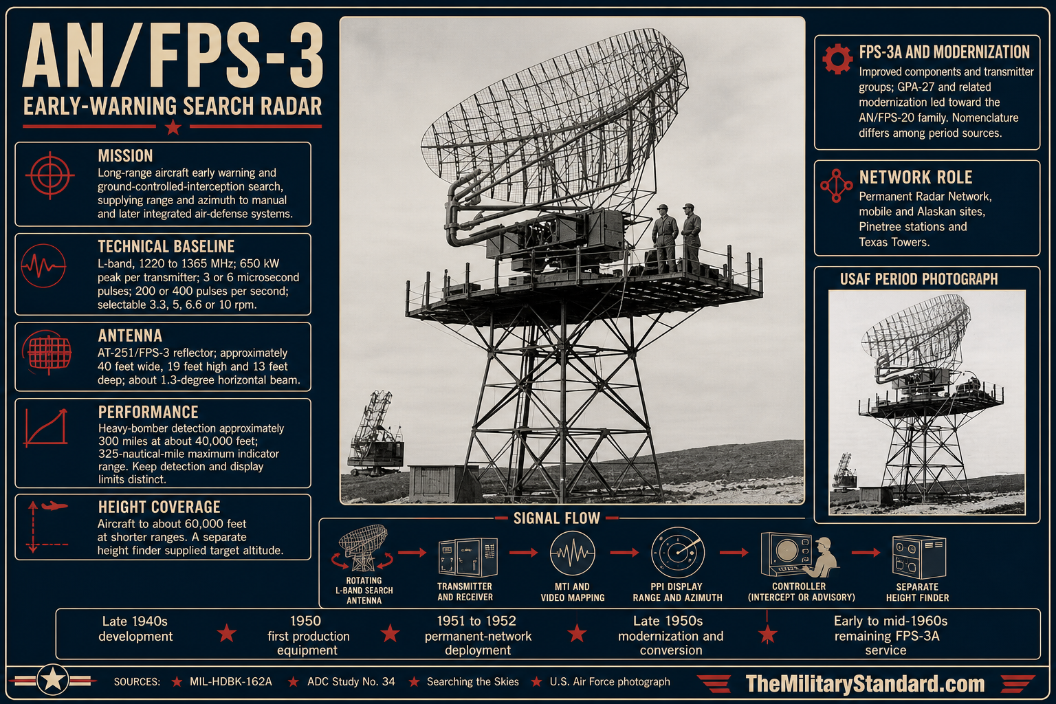
The AN/FPS-3 was a Bendix-built, fixed, two-dimensional aircraft-search radar that helped turn the United States' improvised postwar warning network into a permanent Cold War defense system. Its rotating L-band antenna supplied bearing and range for aircraft approaching defended regions. The set did not by itself measure a target's altitude, so an aircraft-control and warning station normally paired it with a separate height finder and identification equipment. That combination could warn a control center, help classify a contact, and direct interceptor aircraft toward it. The FPS-3 appeared at numerous continental stations, in Alaska and Canada, and on the offshore Texas Towers. Its installed base also provided a path to the substantially modified AN/FPS-20 family.
This history is about the radar set, not a single air force station. Makah, Othello, Fort Custer, Fallon, the Pinetree Line, Alaskan stations, and the Texas Towers are operational examples, but their property histories and later equipment lineages remain distinct. A 1955 continental network accounting cited in an official Army air-defense history lists 64 AN/FPS-3 search radars among the permanent system's principal sets. That is a snapshot of one network and period, not a global production total. It nevertheless establishes the FPS-3 as genuinely widespread in the early network, rather than merely a prototype that happened to appear at a few test sites.
The suffixes are not interchangeable. The 1965 military radar handbook covers AN/FPS-3 and AN/FPS-3A together but says the 3A incorporated OA-398/FPS-3 transmitter groups and other improved components. Air Defense Command's later study uses FPS-3A in a different discussion of the AN/GPA-27 modification and treats an integral upgraded configuration as AN/FPS-20; the Air Force history Searching the Skies introduces still another FPS-3B label in its modernization summary. This documentary inconsistency cannot be solved by assigning every old station photograph a uniform suffix. The equipment history distinguishes the basic FPS-3, later 3A descriptions, and the more extensively modified FPS-20, while preserving the designation actually given by each contemporary site record.
Origins in the postwar defense problem
After World War II, the Army Air Forces and then the independent Air Force faced a warning problem that had changed faster than their ground network. Many wartime radar sets were worn, temporary, or poorly placed for a new threat from long-range Soviet aircraft. Air-defense leaders envisioned a permanent chain of search radars, control centers, communications routes, and interceptor bases. Funding and construction lagged, so the interim Lashup Radar Network carried much of the early burden. The FPS-3 was among the new radars intended to replace that temporary mix with a more capable and standardized search system, although individual stations changed equipment at different times.
The Air Force historical study The Air Defense of the United States explains that Bendix held a joint development-production contract for the AN/FPS-3. It describes the new set as an improvement on the earlier AN/CPS-5, with faster scanning, moving-target indication, video mapping, and more effective radiated power. The study also says that Airborne Instruments Laboratory had a separate antenna-production contract. These were different contractor roles, so naming Bendix as the radar's principal manufacturer does not mean Bendix fabricated every component. The Air Force initially expected delivery in spring 1950, but production delays extended the program well into 1951. Some early equipment was available near the end of 1950; a single early installation date must not be mistaken for the date of general network readiness.
Planning quantities changed as strategic urgency increased. The same Air Force study records an initial expectation of 24 FPS-3 sets for the permanent system. In August 1950, the Air Force informed Continental Air Command that 49 would ultimately be available for air-defense purposes, allowing planners to substitute more FPS-3 sets for older CPS-5 equipment at proposed sites. The Korean War made a weak radar screen less acceptable and accelerated permanent-system construction. A later account's 64 sets in the 1955 continental inventory is not a contradiction to the earlier plans: the figures describe different stages and scopes, not one fixed total procurement quantity. They also omit at least some overseas and northern-line configurations.
The new radar was designed for a particular role within the permanent station. An FPS-3 could search a wide volume for an incoming bomber, but its two-dimensional return could not tell a controller whether that aircraft was at low, medium, or high altitude. The Air Force historical study explicitly contrasts it with AN/CPS-6B, which included a height-finding function. When the FPS-3 was used for ground-controlled interception, separate height-finding equipment was therefore essential. The separation shaped site plans: the main search tower, height-finder tower, operations room, communications facilities, and power plant had to be placed and connected as one air-defense installation.
Physical system and technical baseline
MIL-HDBK-162A, the Defense Department's 1965 radar handbook, calls the FPS-3 and FPS-3A fixed-system long-range radars equipped with moving-target indication. It gives the operating frequency as 1220 to 1365 MHz, with a 5J26 tunable magnetron as the radio-frequency source. Its listed output is 650 kilowatts peak for each transmitter, not a single 650-kilowatt total for a dual-channel installation and not 650 kilowatts of continuous electrical demand. The handbook gives selectable 3 or 6 microsecond pulses and 200 or 400 pulses per second. Those values are handbook ratings for the documented configuration; they do not justify borrowing a different 750-kilowatt figure from descriptions of a related radar or silently mixing measurements from different modifications.
The same handbook describes 360-degree horizontal coverage, approximately 15 degrees of vertical angular coverage, and antenna tilt from one-half degree below to six and one-half degrees above the reference setting. The scanning rate could be selected at 3.3, 5, 6.6, or 10 revolutions per minute. The principal AT-251/FPS-3 reflector has listed bounding dimensions of 480 by 230 by 156 inches. That is approximately 40 feet across its longest listed dimension, but a component bounding box is not a surveyed tower height or a license to draw every visible structural member from imagination. The handbook identifies temperate tower types AB-178/FPS-3 and AB-196/FPS-3, plus an AB-199 family for arctic installations. Different towers and shelters help explain why authentic FPS-3 photographs need not look identical at every site.
The handbook's performance statement is carefully worded: a heavy-bomber-type aircraft could be detected at approximately 300 miles and approximately 40,000 feet, while aircraft at up to about 60,000 feet could be detected at shorter ranges. It separately lists an indicator or presentation scale reaching 325 nautical miles. Detection at a specified height, the outer scale on an operator's indicator, and the theoretical instrumented limit measure different things. It would be misleading to state simply that every aircraft could be found at 325 nautical miles. Terrain masking, radar horizon, weather, target reflectivity, antenna siting, interference, and operator interpretation all affected an actual track.
The set's signal path connected hardware on the tower to personnel and instruments in the operations building. The handbook's system drawing identifies the search antenna and tower, receiver and indicator groups, console, plotting equipment, telephone switchboard, maintenance room, power building, and message center. Related equipment could include AN/GPA-30 video mapping, AN/GPX-7 identification, and an AN/FPS-6-family or other height finder. Moving-target indication helped distinguish moving aircraft returns from some stationary ground or sea clutter, but it did not erase every false return or provide altitude. A radar operator, height-finder crew, identification specialist, and controller still had to combine information into a useful report.
Power and siting were not minor construction details. The handbook advises placing the power shelter away from the antenna and operations shelter to limit noise and vibration, while keeping the latter within the available interconnecting-cable distance. It recommends separation from VHF and especially UHF communications equipment to reduce interference. It also describes commercial power where available and diesel generator support otherwise. Such provisions explain why a permanent FPS-3 site required more than a steel antenna tower. Continuous warning depended on electrical reliability, heating, safe equipment access, maintenance stores, and communications with the direction center during bad weather or a regional power failure.
The continental network in operation
The radar's practical value is visible at Makah Air Force Station, Washington. A National Archives history reports that FPS-3 equipment was installed at Neah Bay late in 1950. The 758th Aircraft Control and Warning Squadron began operating an AN/FPS-3 search radar and AN/CPS-4 height finder in January 1952 after a Lashup site had provided earlier coverage. The search set watched the coastal approach, while the separate height finder supplied the third coordinate needed for aircraft identification and intercept control. Makah's later SAGE service used newer equipment; its 1960s and 1980s radars should not be retroactively labeled FPS-3 simply because the station continued to operate.
The station also shows how equipment and land histories differ. Its operational radar area occupied Bohokus Peak, while its cantonment area was lower and separate, on land leased from the Makah Tribe. The specific 10-acre operational-area figure in the Archives account is a Makah site fact, not an acreage assigned to an FPS-3 set. When the radar changed and the Air Force later reduced its presence, the site's physical and community history continued. An equipment account can use Makah as a verified deployment example without converting the two-dimensional radar into the whole station's identity.
Historic American Engineering Record documentation of Fort Custer's P-67 radar station in Michigan preserves another concrete installation sequence. Its structures built around 1950-1951 included an FPS-3 primary radar tower, operations building, emergency power building, heating plant, transmitter and receiver buildings, support and security structures. A separate height-finder tower appeared as the station developed. The preservation study records the original FPS-3 tower becoming an FPS-20 prime-search tower during later modernization. This is evidence of a conversion at a particular complex, not proof that the original FPS-3 continued unchanged until the later tower was removed.
The Army's retrospective air-defense history describes 64 FPS-3s, seven CPS-6Bs, and four FPS-10s among the permanent system's main search radars in 1955. It also emphasizes a network weakness: the high-site, long-range screen was not very effective against low-altitude aircraft. The proposed AN/FPS-14 gap fillers addressed that problem with many small unattended stations between the heavy-radar sites. Thus, even as the FPS-3 formed a large share of the principal long-range network, it was not a comprehensive solution to every flight path. The high-altitude bomber threat, terrain-limited low-level approach, and later missile threat imposed different sensor requirements.
The radar's use was not confined to the first permanent-system construction phase. A National Park Service record for Naval Air Station Fallon says the Air Force's adjacent Fallon Air Force Station initially used mobile AN/MPS-7 and AN/MPS-14 equipment and briefly had an AN/FPS-3 assigned in 1959. This short tenure is useful because it prevents a false binary division between fixed permanent radars and mobile-station history. Equipment could be moved, tested, replaced, or reclassified while a station's role continued. A snapshot of a radar inventory needs a date, not just an installation name.
Alaska and the northern defense line
Alaskan Air Command faced a demanding geographic problem. Its radar chain had to watch likely approaches from the north and west across immense distances, in severe weather, and with difficult transport and maintenance. A NORAD/CONAD history records 13 AN/FPS-3s, two AN/CPS-6Bs, and three AN/FPS-8s at Alaska's 18 operating heavy-radar stations by the end of 1958. The count describes that network at that date and does not mean the FPS-3 operated at every Alaskan station. These radars fed regional direction and control, and their tracks were useful only when communications survived across the remote stations and relay network.
The same NORAD/CONAD history explains why modernization was urgent. Planners wanted high-altitude continuity from Cape Lisburne toward King Salmon and a link to the Aleutian extension of the Distant Early Warning Line. AN/GPA-27 modification equipment would convert selected FPS-3 sets to AN/FPS-20 capability. Funding shortages cut the Alaska program from a proposed 13 conversions to nine; Middleton Island, Ohlson Mountain, Tin City, and Northeast Cape were removed from that particular package. By the end of 1958, Sparrevohn, Indian Mountain, King Salmon, Campion, Tatalina, and Cape Lisburne had converted, with Cape Newenham, Cape Romanzof, and Wales still scheduled. These are NORAD's program and status statements, not a guarantee that all remaining installations were finished on one shared day.
This Alaskan example shows that the upgrade was driven by geography and threat as well as laboratory performance. Commanders worried that gaps between radar coverage, direction centers, DEW Line warning, and F-102 interceptor routes would leave defended target areas exposed. The official history explicitly records the operational consequences of losing four modification kits. A bare catalog statement that an FPS-3 became an FPS-20 misses the priority decisions, construction work, and temporary asymmetry of a live defense network being rebuilt around continuing operations.
The AN/FPS-3 also served in the United States-Canadian Pinetree Line, though site records show several suffixes and operators. A contemporary U.S. Air Force historical report for Frobisher Bay identifies its AN/FPS-3(C) as the primary search radar during the fourth quarter of 1954, accompanied by an AN/TPS-502 height finder and AN/GPX-7 identification set. The report states that the primary radar operated for 2,028 hours and 41 minutes, approximately 92 percent of the quarter, with scheduled and emergency maintenance accounting for much of the balance. This is a dated site readiness measure, not an intrinsic uptime guarantee for every FPS-3.
Frobisher Bay's 1956 reports give rare insight into everyday maintenance. They describe correcting terrain-screening-angle charts that did not agree with measured azimuth sectors, and failures involving cracked capacitors, magnetron circuits, high-voltage interlocks, a damaged transmit-receive cavity, and a leaking pulse transformer. At least one needed part was not available locally and had to enter the supply chain. These details demonstrate why published detection distance could differ from practical coverage and why isolated northern stations needed skilled radar-maintenance sections. A paper range figure did not repair a magnetron or correct an erroneous site screening chart.
NORAD/CONAD's late-1958 Canadian status review said 15 Canadian-site AN/FPS-3s were planned for conversion to AN/FPS-20 through AN/GPA-27 additions. It recorded Pagwa River as one completed example by that year's end, while other programs substituted different radar types. The review illustrates how a common designation could remain in several stages across a large line: original FPS-3, locally suffixed sets, sets under modification, and new or replacement FPS-20 equipment. The American and Canadian station histories should not be collapsed into a single inventory count or universal modernization date.
Offshore warning and the Texas Towers
The Texas Towers extended the early-warning screen seaward from the northeastern United States. MIT Lincoln Laboratory's SAGE history describes the operational offshore platforms as carrying an AN/FPS-3 search radar and two AN/FPS-6 height finders on the upper deck. Only Texas Towers 2, 3, and 4 were built of five approved positions. The principal point for FPS-3 history is not that a tower was another routine station; it is that the radar and its height-finding companions operated on a manned ocean platform subject to sea motion, salt exposure, difficult logistics, and weather. The hardware remained part of the same air-defense detection and reporting architecture, but its physical operating environment was radically different from a continental mountaintop.
Tower-specific attribution still needs restraint. Later site summaries sometimes call Texas Tower 2's original search set FPS-3A, while broader SAGE descriptions call the family FPS-3. The original equipment and subsequent modifications on each offshore tower require dated records before a suffix can be fixed with certainty. The towers' major historical events, including Texas Tower 4's 1961 loss, are installation and personnel histories; they should not be recast as accidents of the FPS-3 radar itself. Their inclusion here shows the reach of the equipment family into offshore warning, not that every radar aboard those platforms was identical or served to the same date.
Modernization, SAGE, and designation problems
Jet bombers flying higher, at greater speed, and with electronic countermeasures challenged early postwar search radars. Air Defense Command pursued the Semi-Automatic Ground Environment, which needed radar data in suitable form for computers and direction centers rather than relying entirely on manually transmitted plots. The FPS-3 was an effective manual-era radar, but its original electronics were not the endpoint of that automated system. Modernization addressed high-altitude coverage, processing and presentation, reliability, and compatibility with the changing command network. Some installations replaced their FPS-3 outright with a different radar; others changed significant portions of the existing set and then used a new designation.
The AN/GPA-27 program is central to that transition. ADC Historical Study No. 34 described the proposal in the mid-1950s as modifying an FPS-3 to search to about 65,000 feet. NORAD's Alaskan and Canadian histories document actual planned and completed conversions to AN/FPS-20 during 1958. The modification designation refers to a package and work, while AN/FPS-20 names a later radar configuration. A station that opened with FPS-3 and later reported FPS-20 may have retained major physical infrastructure, such as a tower or operations building, yet changed enough electronics and performance that its subsequent service is not basic FPS-3 service.
The suffix FPS-3A is more troublesome than a simple family diagram suggests. The 1965 handbook's distinction turns on OA-398/FPS-3 transmitter groups and improved components. ADC Study No. 34 uses FPS-3A in connection with the GPA-27 high-altitude modification and identifies an integral configuration as FPS-20. Searching the Skies describes a GPA-27-modified FPS-3B in one broad account. These source differences could reflect changing nomenclature, local modifications, or retrospective simplification; the reviewed evidence does not settle every boundary. The safest rule is to quote a source's own designation, tie it to a date and station, and describe the documented work rather than silently asserting that every 3A, 3B, and FPS-20 was the same hardware.
The mobile AN/MPS-7 belongs to the development family but not to the identical equipment record. It adapted an FPS-3-derived long-range search capability for the Air Defense Command's Mobile Radar Program. The relationship matters because mobile sites later entered the permanent network and some MPS-7 equipment also underwent AN/GPA-27-family improvements. Nevertheless, a mobile MPS-7 deployment should remain identified as MPS-7 unless a source documents its conversion. In the same way, the FPS-20's numerous later anti-jam and frequency-diversity descendants must not all be called FPS-3 simply because their engineering lineage began there.
Retirement and surviving evidence
An official Army chronology states that the last basic FPS-3 long-range radar was phased out of the Air Defense Command network in July 1964. A September 1965 contemporary Air Force and Space Digest account identifies that last ADC set as the radar at Havre Air Force Station, Montana. That is a useful endpoint for the ADC inventory, not evidence that every foreign-operated, locally suffixed, or already converted descendant ceased to exist in that month. The original radars disappeared by a mixture of conversion, replacement, and station closure. Makah went on to other search-radar generations; Fort Custer's original search tower served an FPS-20; Fallon used its FPS-3 briefly; Canadian and Alaskan sites followed differing schedules.
No complete publicly verified operational FPS-3 set has been identified in the present source review. The 1965 handbook's component drawings and system diagram preserve its engineering arrangement; the USAF photograph published in Searching the Skies preserves an authentic appearance; National Archives and historic-engineering records preserve station context. Some former radar installations retain towers, foundations, operations buildings, power houses, or radomes, but surviving site fabric is not proof that a working FPS-3 remains within it. The distinction matters particularly for sites where the same tower supported an FPS-20 or another successor radar after the original set was converted or removed.
The FPS-3's historical importance lies in the system it made practical. It replaced many temporary postwar arrangements with a long-range search set suitable for permanent aircraft warning, supplied a large share of the 1950s continental screen, and served harsh northern and offshore positions. Its limits also drove the next stage: separate height-finding, low-altitude gap fillers, higher-altitude modification, and computer-compatible network equipment. The story is not one of a radar simply becoming obsolete; it is a record of how the North American defense network changed around a heavily used first-generation permanent sensor.
Technical summary
- Designation
- AN/FPS-3 fixed two-dimensional search radar; AN/FPS-3A designation is source- and configuration-dependent.
- Principal manufacturer
- Bendix Radio Division of Bendix Aviation Corporation; Airborne Instruments Laboratory held a separate early antenna-production contract.
- Principal user
- United States Air Force air-defense organizations; U.S. and Canadian northern-line use is documented.
- Frequency
- 1220-1365 MHz, L-band, per MIL-HDBK-162A.
- Peak RF output
- 650 kW per transmitter in the 1965 handbook configuration; do not treat as average RF or station electrical demand.
- Pulse
- selectable 3 or 6 microseconds at 200 or 400 pulses per second, per handbook.
- Antenna
- AT-251/FPS-3 reflector, handbook bounding dimensions 480 x 230 x 156 inches; temperate and arctic tower options.
- Rotation
- selectable 3.3, 5, 6.6, or 10 rpm, per handbook.
- Search coverage
- 360 degrees in azimuth; performance target-dependent and terrain-limited.
- Illustrative performance
- heavy bomber about 300 miles at 40,000 feet; up to about 60,000 feet at shorter ranges; 325-nautical-mile indicator scale is a different measure.
- Height information
- required a separate height finder for GCI; the FPS-3 itself was a two-dimensional search radar.
- Broad U.S. ADC phase-out
- last basic FPS-3 removed from ADC radar network in July 1964 according to an official Army chronology; converted FPS-20 descendants are distinct.
Chronology
- Late 1940s Air Force permanent-system planning identifies a need for a new long-range search radar beyond the temporary postwar Lashup equipment.
- 1950 Bendix FPS-3 development-production expectations slip, while Air Force planning expands from 24 to 49 intended air-defense sets.
- 1950-07 Korean War urgency leads the Air Force to accelerate construction of permanent radar stations.
- 1950-late National Archives account dates AN/FPS-3 equipment installation at Neah Bay, Washington.
- 1951 The permanent radar network begins receiving FPS-3 equipment at multiple new or converted stations.
- 1952-01 The 758th AC&W Squadron operates FPS-3 search and CPS-4 height-finding radars at Neah Bay after Lashup coverage.
- 1952 Fort Custer's P-67 station has an FPS-3 primary search tower within its new permanent-site complex.
- 1954-10 to 1954-12 Frobisher Bay's USAF report records its FPS-3(C) primary radar operating 2,028 hours and 41 minutes during the quarter.
- 1955 Retrospective official network accounting identifies 64 FPS-3s as principal search radars of the continental permanent system.
- 1956 Frobisher Bay maintenance records document FPS-3 screening-angle corrections and multiple electronics and supply problems.
- 1956-1957 ADC plans AN/GPA-27 modernization for greater high-altitude coverage and the later FPS-20 configuration.
- 1958 Alaska's operating heavy-radar network includes 13 FPS-3s, with funding limiting AN/GPA-27 conversions to nine of them.
- 1958-07 NORAD's Canadian status report records Pagwa River's FPS-3 as converted to FPS-20, the first completed conversion reported in that review.
- 1958-12-31 NORAD records six Alaskan FPS-3-to-FPS-20 conversions operating and three still scheduled.
- 1959 Historic American Engineering Record notes a brief FPS-3 assignment at Fallon Air Force Station, Nevada.
- Late 1950s The original Fort Custer FPS-3 search tower supports an FPS-20 as that station modernizes.
- Early 1960s Makah and other early FPS-3 stations transition to newer radars and computerized SAGE-era reporting.
- 1964-07 Official Army chronology records the last basic FPS-3 phased out of the Air Defense Command radar network; a contemporary Air Force account identifies Havre Air Force Station, Montana, as that site.
- 1965-12-15 MIL-HDBK-162A publishes a retrospective technical entry for the FPS-3 and FPS-3A family.
- 1997 USAF-sponsored Searching the Skies preserves a period radar photograph and summarizes the family's Cold War role.
Historical photographs and drawings
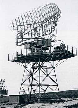
The surviving USAF photograph, originally published in Searching the Skies, shows the Bendix FPS-3 antenna, platform, and tower. It establishes equipment appearance, but not a particular station or suffix.
Photograph provenance and public-domain record. The 1965 Defense Department handbook includes a system diagram and component entry.

Information sources (17)
- PDFDepartment of Defense, MIL-HDBK-162A / TM 11-487C-1, United States Radar Equipment, AN/FPS-3 and AN/FPS-3A entry
SOURCE FOR purpose, Bendix attribution, component names and dimensions, radio-frequency and pulse characteristics, performance, siting, power, and associated height-finding and identification equipment.
- PDFUnited States Air Force, The Air Defense of the United States, a Study of the Work of ADC and Its Predecessors Through June 1951
SOURCE FOR postwar permanent-network planning, Bendix contract, Airborne Instruments Laboratory antenna role, production delay, 24-to-49-set planning change, and FPS-3 versus CPS-6B height-finding distinction.
- PDFUnited States Air Force, The Development of Continental Air Defense to 1 September 1954, Historical Study 26
SOURCE FOR permanent-network origins, the Korean War construction acceleration, and the FPS-3 place among improved postwar radars.
- WEBUnited States Army Center of Military History, History of Strategic Air and Ballistic Missile Defense, 1956-1972, Volume II
SOURCE FOR the 64-FPS-3 permanent-system inventory snapshot, low-altitude coverage deficiency, gap-filler response, and July 1964 ADC phase-out statement.
- PDFAir Force and Space Digest, Air Defense Command report, September 1965
SOURCE FOR the contemporary identification of Havre Air Force Station, Montana, as the site of the last FPS-3 to leave the ADC system in July 1964.
- PDFAir Defense Command, Radar Programs for Air Defense 1946-1966, Historical Study 34
SOURCE FOR AN/GPA-27 high-altitude modernization and the study's own FPS-3A and FPS-20 nomenclature.
- PDFNorth American Air Defense Command and Continental Air Defense Command, History January-June 1958
SOURCE FOR the Alaskan 13-set FPS-3 count, budget-reduced modification program, and station schedules.
- PDFNorth American Air Defense Command and Continental Air Defense Command, History July-December 1958
SOURCE FOR six completed and three pending Alaskan FPS-3 conversions, Canadian 15-site modification plan, and Pagwa River status.
- WEBNational Archives, A Front Line of Defense: The 758th Radar Squadron and Makah Air Force Station
SOURCE FOR the Neah Bay FPS-3 installation and 1952 paired CPS-4 operation, site layout, later SAGE and radar succession.
- PDFNational Park Service, HAER MI-87-A, Fort Custer Military Reservation P-67 Radar Station
SOURCE FOR the original FPS-3 tower, permanent-site facilities, and subsequent FPS-20 conversion at a specific station.
- PDFNational Park Service, HABS NV-33-C, Naval Air Station Fallon Power Plant
SOURCE FOR Fallon Air Force Station's brief 1959 FPS-3 assignment in the larger radar-site evolution.
- WEBUnited States Air Force Historical Division, Frobisher Bay fourth-quarter 1954 station report, preserved by Canadian Radar History Project
SOURCE FOR FPS-3(C) deployment, supporting radars, and dated operating and maintenance hours.
- WEBUnited States Air Force Historical Division, Frobisher Bay 1956 station reports, preserved by Canadian Radar History Project
SOURCE FOR radar screening-angle correction and documented magnetron, capacitor, interlock, and supply problems.
- WEBMIT Lincoln Laboratory, SAGE: Semi-Automatic Ground Environment Air Defense System
SOURCE FOR the Texas Towers' offshore FPS-3 and FPS-6 arrangement and the three built platforms.
- PDFUnited States Air Force, Searching the Skies: The Legacy of the United States Cold War Defense Radar Program
SOURCE FOR broader air-defense context, historic FPS-3 photograph, high-altitude concern, and retrospective modernization nomenclature requiring caution.
- PDFHeadquarters Aerospace Defense Command, Historical Data 1946-1973
SOURCE FOR the compact ADC equipment classification of FPS-3 as medium-range search, which differs in purpose and terminology from the long-range handbook description.
- WEBUnited States Air Force, Bendix AN/FPS-3 radar photograph, published in Searching the Skies and archived by Wikimedia Commons
SOURCE FOR: Period photograph and public-domain provenance used to check the graphic reconstruction and reproduced in the photo section.