
Texas Tower No. 2 / Georges Shoal Radar Station, Massachusetts
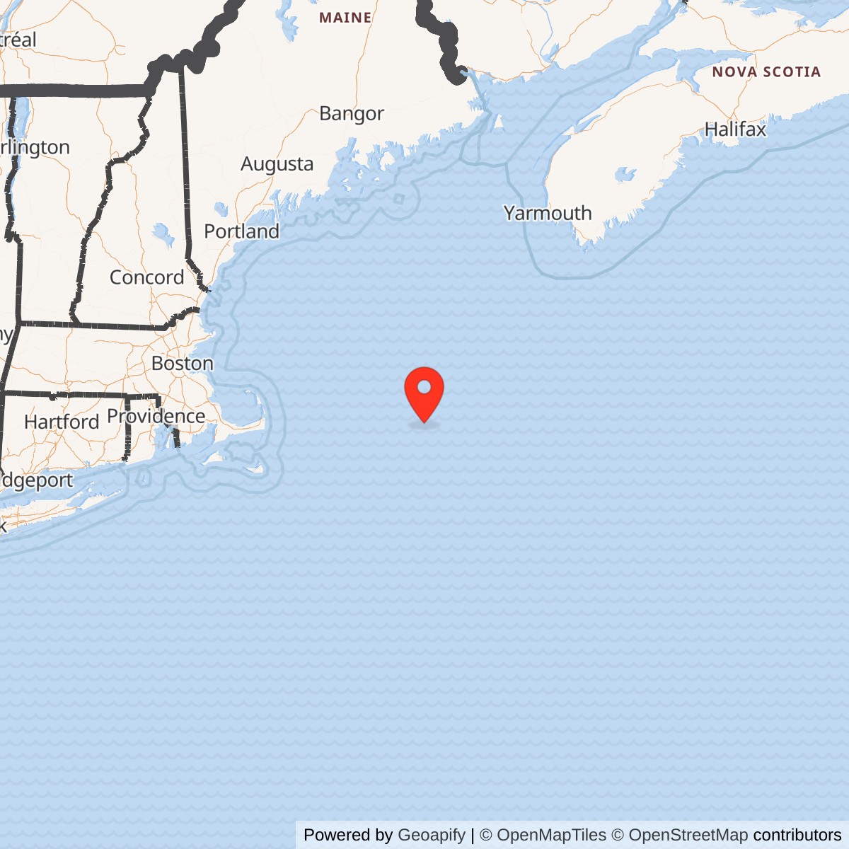
Longitude: -67.783333
Site Number: TT-2
Official Base Website: Submerged remains of Texas Tower No. 2
Current Role: Submerged steel and concrete wreck and charted navigation obstruction on Georges Shoal. No current Air Force use, public access regime, tower-specific environmental response project, or modern preservation management plan was located. NOAA charts the remains at 41.696667, -67.773333, separately from the historical operating point.
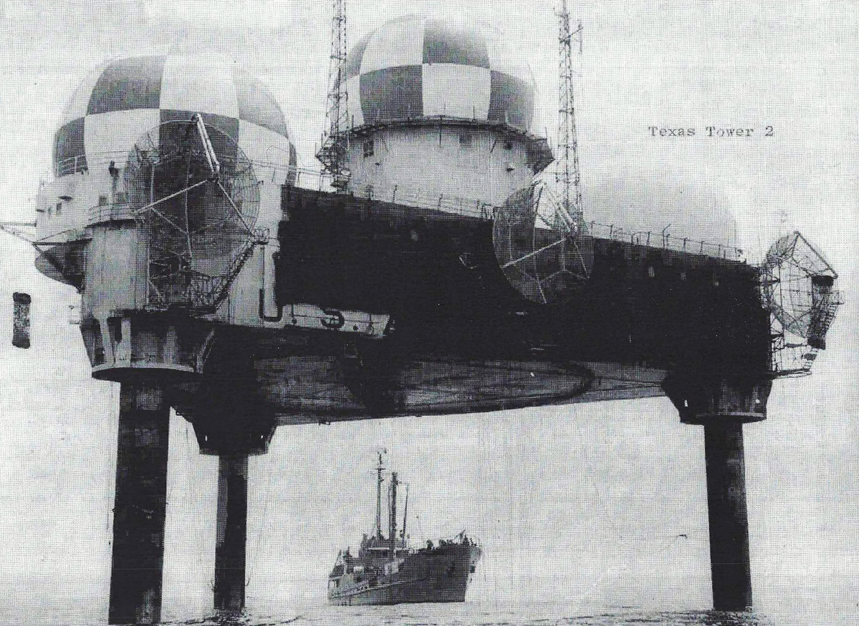
Texas Tower No. 2 was a continuously staffed United States Air Force radar station built on an artificial steel platform above Georges Shoal on Georges Bank, far east of Cape Cod. It was the first of three completed Texas Towers and the only one built to the original short-leg configuration. The tower extended continental aircraft warning, identification, height finding, and ground-controlled interception coverage into the Atlantic, first through manual reporting and from September 1958 through the Semi-Automatic Ground Environment. Its Air Defense Command site designation was TT-2, and its informal radio call sign was Foolhardy.
The installation existed because the radar horizon limited what shore stations could see. Soviet bombers approaching at high altitude could be detected far offshore, but aircraft flying low remained hidden until they came within line of sight of a coastal antenna. Air Defense Command sought more warning time by moving radar seaward. Texas Tower No. 2 became the operational test of that concept, combining long-range search radar, two height finders, identification equipment, weapons-control consoles, tropospheric-scatter communications, electrical generation, housing, medical support, and aviation and marine logistics on a single isolated structure.
The tower's history has several different starting dates, each describing a separate milestone. Air Defense Command activated the first TT-2 operating organization on December 2, 1955, when it accepted beneficial occupancy. The site achieved limited operational readiness on May 7, 1956, and the command's consolidated historical table records manual operations beginning in May. It became fully operational manually on April 17, 1958, then became operational in SAGE in September 1958. These dates are complementary rather than contradictory and must not be reduced to a single unexplained opening date.
Texas Tower No. 2 was decommissioned on January 15, 1963. The decision followed the loss of Texas Tower No. 4, recurring concern about offshore structural risk, high operating cost, changing air-defense priorities, and the impending Airborne Long Range Input system. The abandoned platform was demolished with explosives in September 1963. Its remains came to rest on Georges Shoal and are still charted by NOAA as a submerged obstruction, leaving the installation's final physical record on the seabed rather than on land.
Installation Identity, Name, and Scope
Texas Tower No. 2 and Georges Shoal Radar Station are names for the same staffed offshore installation. Contemporary Air Defense Command records normally use Texas Tower No. 2, TT-2, or George's Shoal, with the possessive spelling found in period tables. Modern geographic authorities generally spell the feature Georges Shoal and the larger bank Georges Bank. The installation was neither a vessel nor a temporary construction barge once accepted by the Air Force. It was a fixed radar station with an assigned crew, operating mission, parent station, support squadron, site designation, communications links, utilities, accommodations, and continuing readiness requirements.
The installation must be distinguished from its two shore parents. North Truro Air Force Station, site P-10 and later Z-10, furnished the operational parent squadron and integrated TT-2 into the radar network. Otis Air Force Base supported the tower through the 4604th Aircraft Control and Warning Squadron and later the 4604th Support Squadron (Texas Towers). Those shore installations contained command, maintenance, transport, supply, and administrative functions that could not be maintained efficiently offshore, but neither was physically part of TT-2.
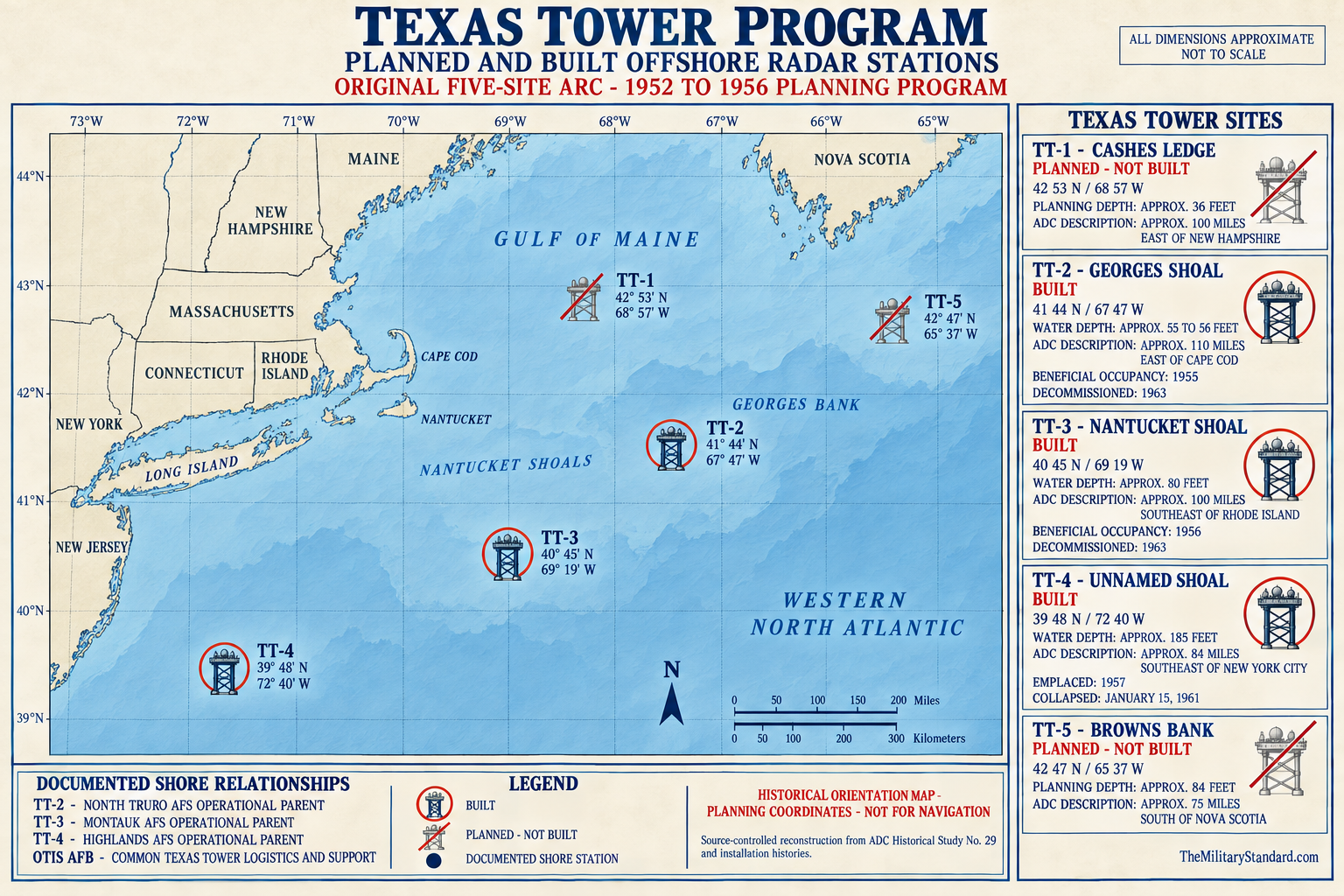
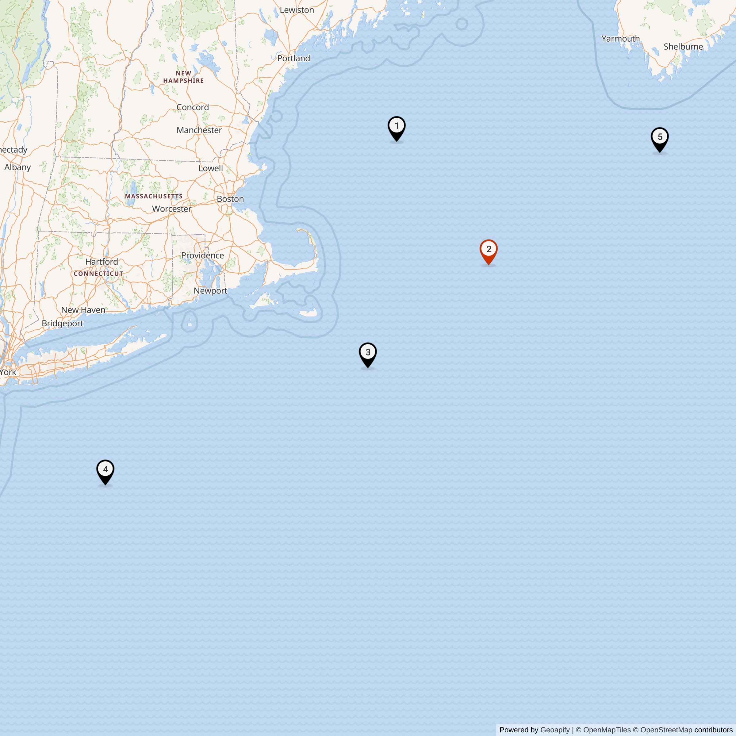
Texas Tower No. 2 must also be separated from the broader five-site proposal. Lincoln Laboratory and Air Defense Command planning identified TT-1 at Cashes Ledge, TT-2 at Georges Shoal, TT-3 at Nantucket Shoal, TT-4 at Unnamed Shoal, and TT-5 at Browns Bank. All five were authorized in the early program, but only TT-2, TT-3, and TT-4 were built. TT-1 and TT-5 were canceled before fabrication produced staffed installations because coastal radar improvements were expected to cover their sectors.
Location, Offshore Jurisdiction, and Coordinates
The operating site stood on Georges Shoal in the shallow central danger area of Georges Bank, approximately 110 miles east of Cape Cod by the distance used in Air Force historical records. Some official summaries instead describe the tower as 137 miles east of Cape Cod, reflecting a different shore reference or route measurement. The difference should not be interpreted as evidence for two sites. Both descriptions refer to the same remote Atlantic station above a shoal where the water was about 55 to 56 feet deep.
The Air Force unit-history compilation gives the historical station coordinate as 41 degrees 44 minutes north latitude, 67 degrees 47 minutes west longitude, or approximately 41.733333, -67.783333. That point is used as the representative operating-location coordinate because it identifies the staffed radar station during its military life. It is not represented as a surveyed caisson-center position, modern wreck fix, legal boundary, anchorage, safe approach, or diving coordinate. Period map scales and coordinate rounding limit precision.
The current NOAA Coast Pilot charts the remains of an old Texas tower as a submerged obstruction at 41 degrees 41.8 minutes north latitude, 67 degrees 46.4 minutes west longitude, or approximately 41.696667, -67.773333. The offset from the historical operating point is significant and is preserved explicitly. It may reflect the final demolition and sinking location, historical coordinate rounding, charting methods, or a combination of those factors. The NOAA point is the authoritative modern navigation reference for the wreck, while the Air Force point is retained for the operating installation.
Administrative state labeling is necessarily qualified because TT-2 stood far outside the land territory of any state. The Air Defense Command table labels George's Shoal, NY, while most later accounts associate the station with Massachusetts through Cape Cod, North Truro, and Otis. This record uses Massachusetts as the catalog state for consistency with that operational geography and parent relationship, but identifies the actual location as the Atlantic Outer Continental Shelf on Georges Bank. No claim of Massachusetts state ownership or jurisdiction over the site is intended.
Strategic Requirement and Program Origins
The Texas Tower program grew from the continental air-defense emergency of the early 1950s. Soviet long-range bombers, atomic weapons, and the possibility of attacks across the North Atlantic compelled the United States to build overlapping radar belts. Shore stations improved coverage over land and along the coast, but radar line of sight left a low-altitude warning gap seaward. An approaching bomber could exploit the curvature of the earth and remain below a coastal radar horizon until much closer to its target.
MIT Lincoln Laboratory examined the seaward-extension problem while developing the Cape Cod System and the larger SAGE concept. On August 1, 1952, the laboratory outlined a fixed offshore platform approach modeled in general appearance on oil structures used in the Gulf of Mexico. Moving powerful radars onto shallow offshore shoals promised to extend detection and control geometry without requiring foreign territory or a continuous fleet of picket ships. The nickname Texas Tower came from the oil-platform resemblance, not from the towers' geographic location.
The Air Force and Navy divided responsibility according to institutional strengths. Air Defense Command established the military requirement and would operate the radar system. The Navy Bureau of Yards and Docks conducted surveys and managed engineering, design specifications, and construction contracting because it possessed offshore and maritime construction expertise. Lincoln Laboratory contributed system concepts and technical development. This arrangement made the project possible, but it also created a complex chain of design, contracting, acceptance, maintenance, and operational responsibility that became more controversial after TT-4 collapsed.
Program planners initially expected five platforms spaced along the northeastern approaches. TT-1 at Cashes Ledge and TT-5 at Browns Bank would have extended the arc at its ends, while TT-2, TT-3, and TT-4 covered Georges Bank, Nantucket Shoal, and the New York approaches. The five were authorized in autumn 1953, with funds programmed in fiscal years 1954 and 1955. Construction experience, cost, changing coverage from shore stations, and evolving radar plans soon narrowed the concept to three completed towers.
Design and Physical Layout
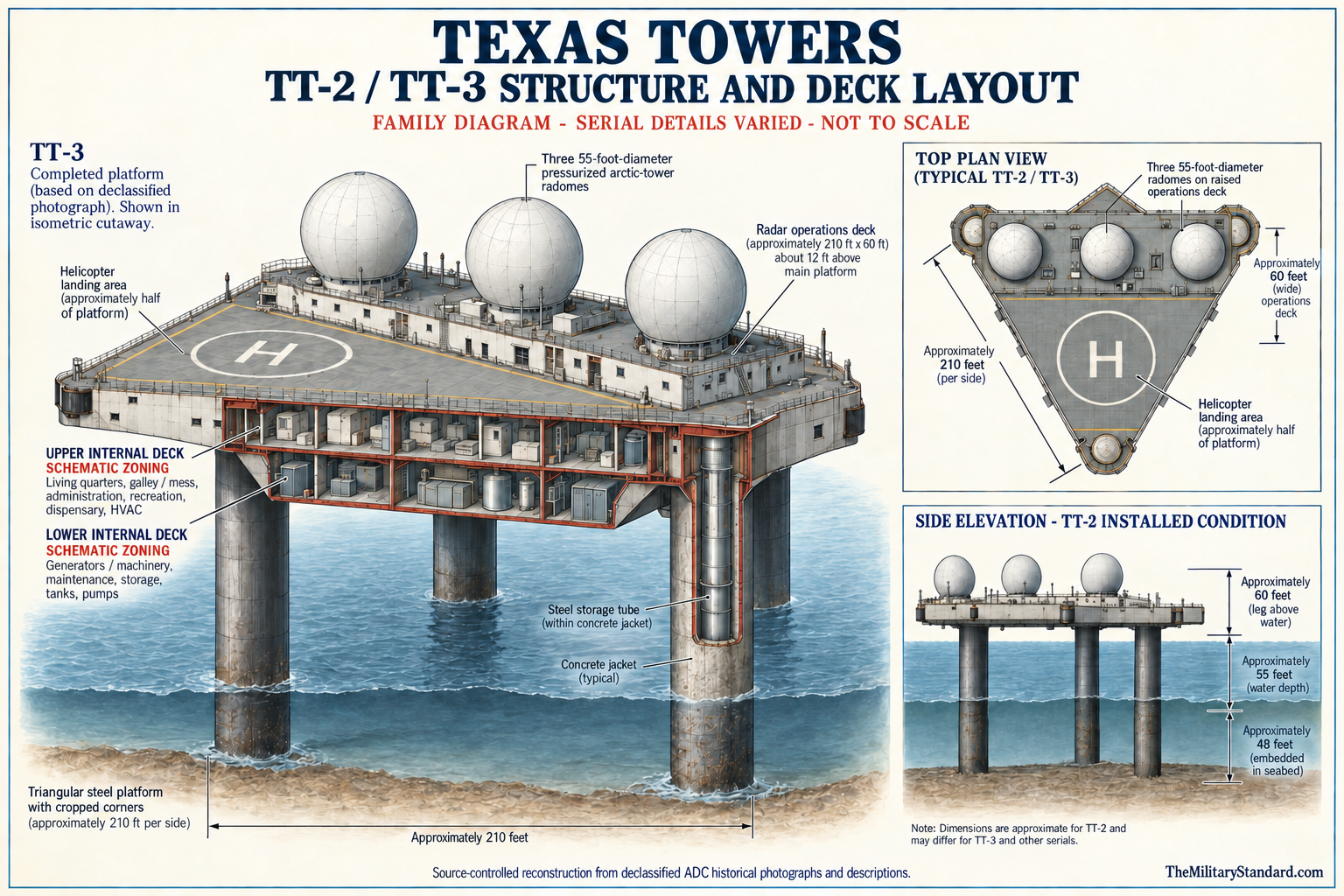
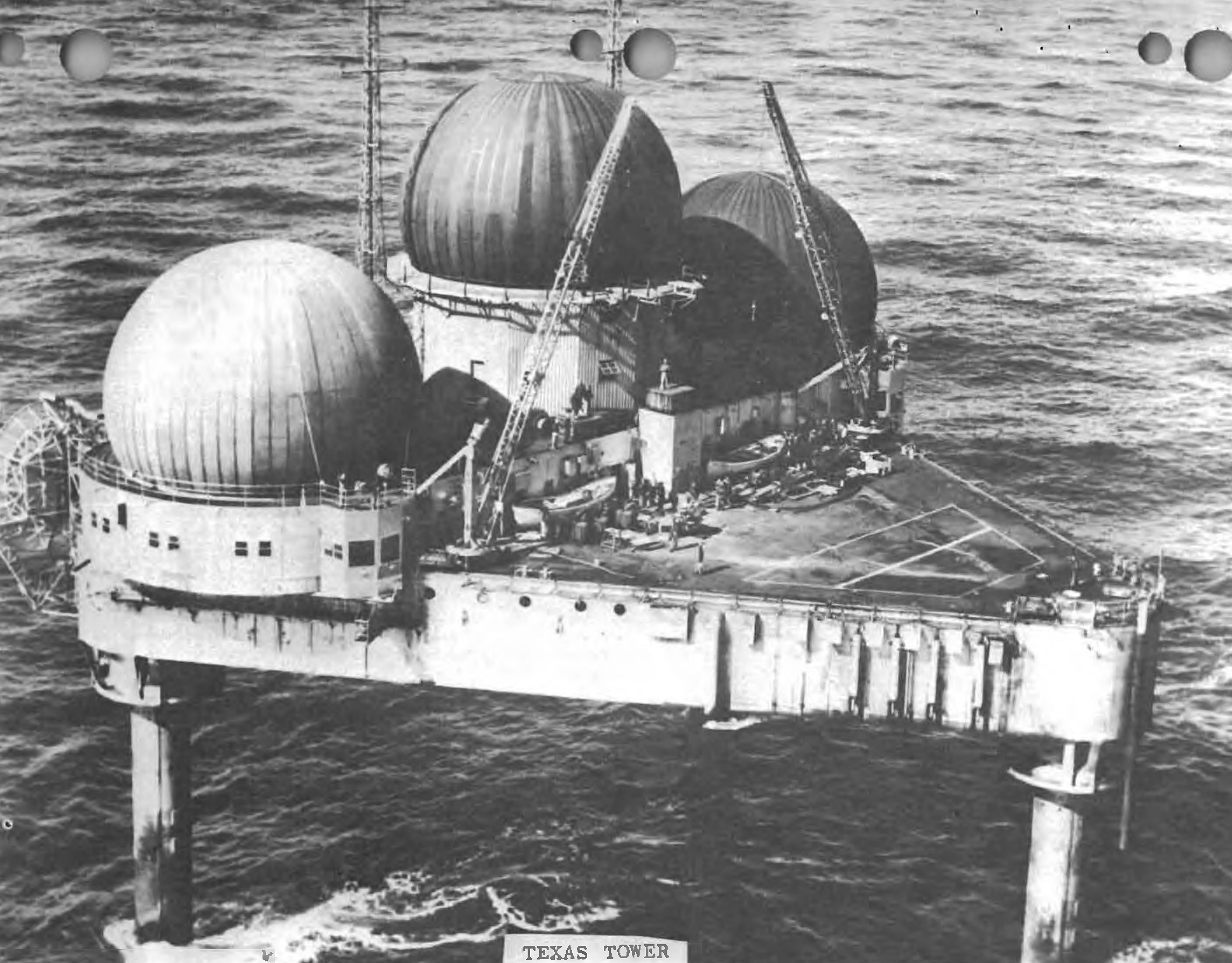
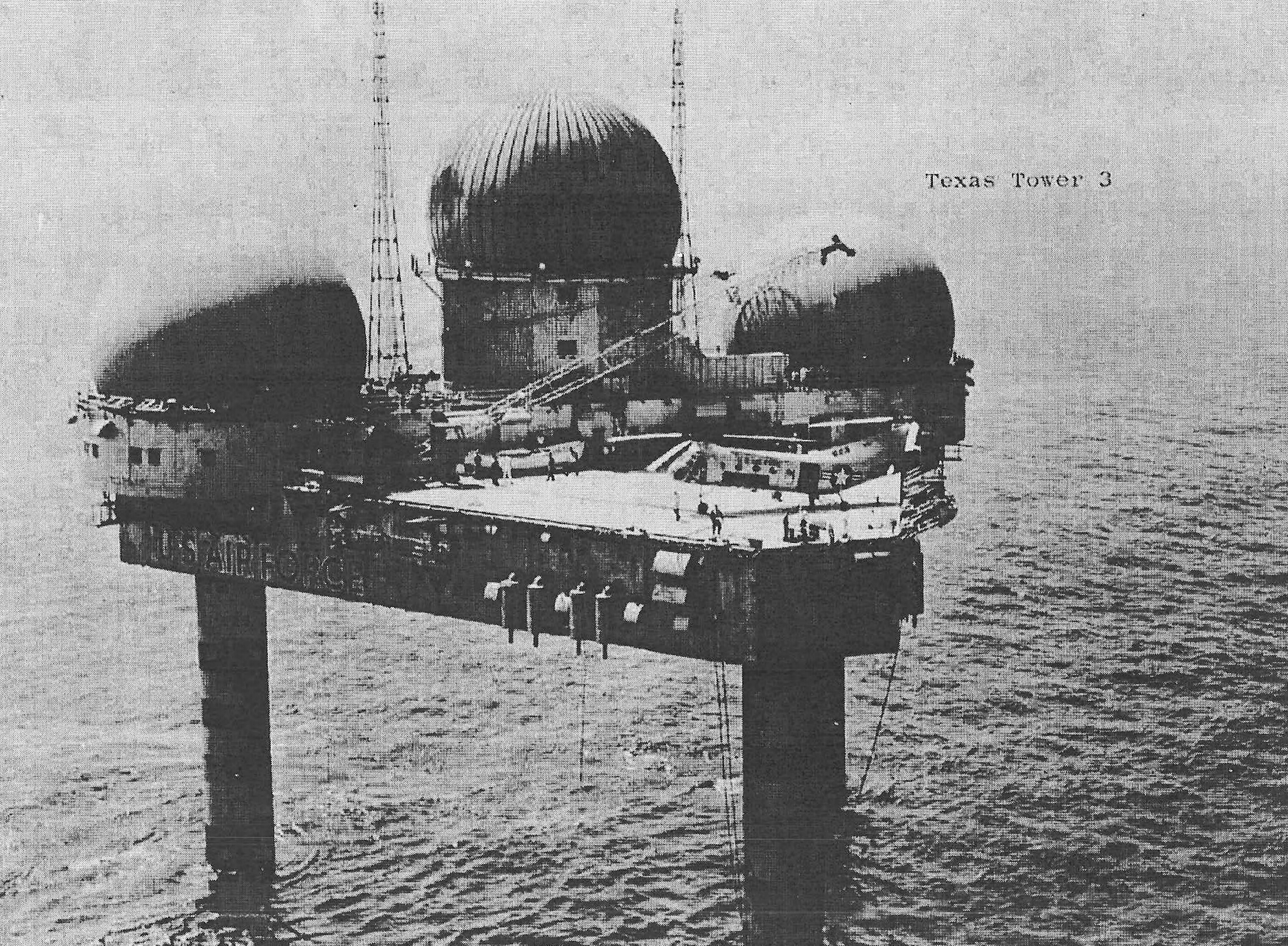
Texas Tower No. 2 was an equilateral triangular steel platform with cropped corners and sides approximately 210 feet long. Its enclosed platform body was about 20 feet deep and provided roughly half an acre of usable surface. The mass of the platform with its installed equipment was reported at about 6,500 tons. The design had to function as a radar station, dormitory, power plant, communications center, warehouse, aviation landing area, and small medical and administrative post while surviving waves, wind, corrosion, vibration, and salt exposure.
The platform was divided into working and living levels. The bottom deck held maintenance areas, pumps, tanks, machinery, and storage. The next level contained sleeping quarters, galley and mess, offices, heating and air-conditioning plant, recreation space, food storage, dispensary, and library. Above those compartments, part of the roof formed a helicopter landing area. A raised operations deck approximately 210 feet long and 60 feet wide occupied the other portion and contained surveillance, control, and electronic equipment spaces.
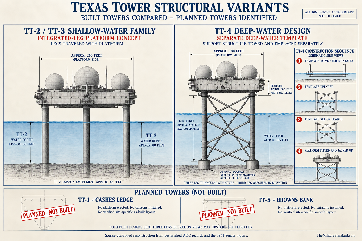
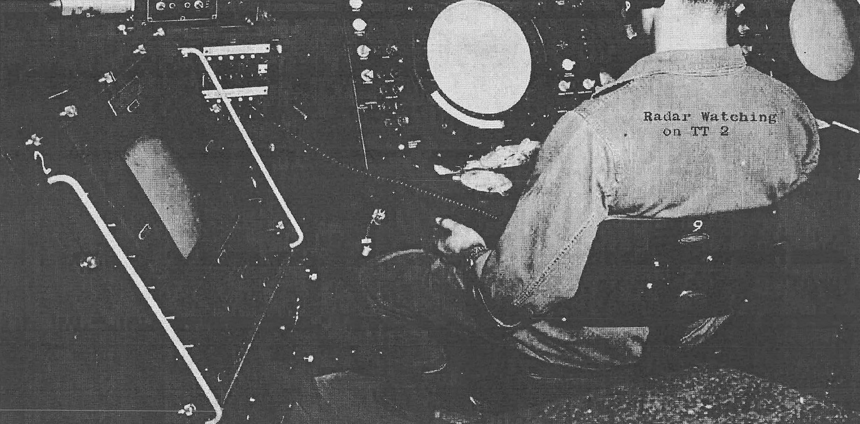
Three pressurized radomes stood above the operations deck. One sheltered the search radar and two housed height finders, creating the most recognizable outline of the station. Pressurization protected the antennas from weather and reduced wind loading while permitting rotation inside the domes. The visible arrangement was not decorative. It embodied the operating sequence in which a search radar found and tracked a target, height-finder crews measured altitude, identification equipment assisted classification, and weapons controllers passed a usable air picture to the defense network.
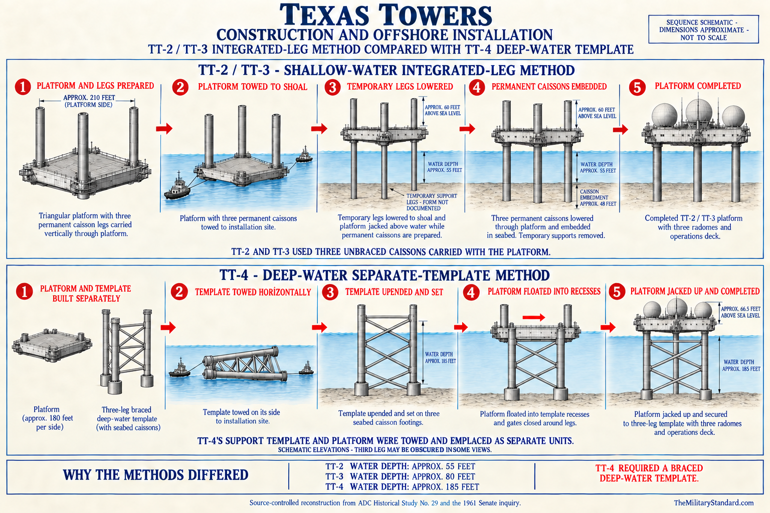
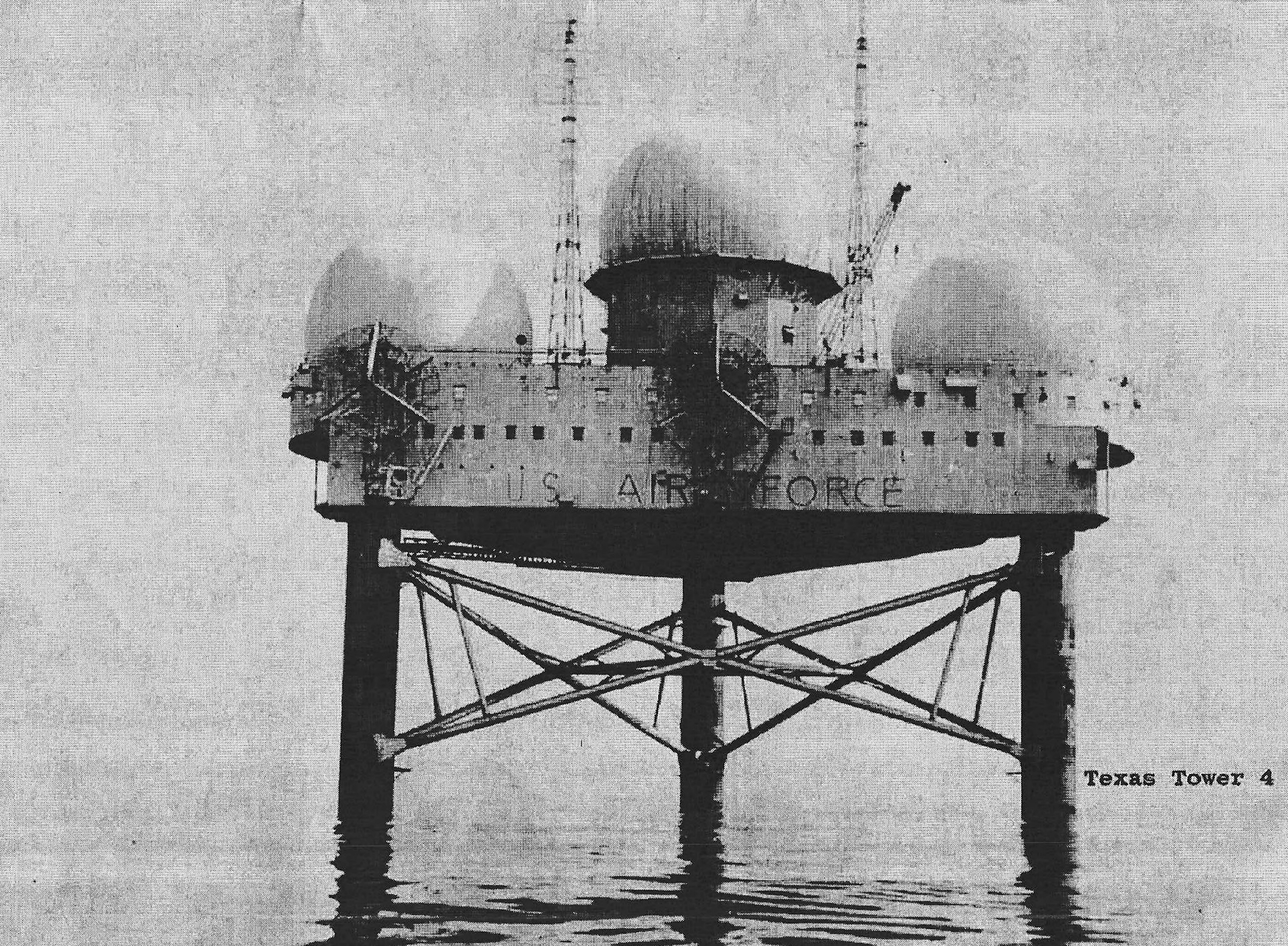
The structure stood on three tubular caisson legs more than 160 feet long. Approximately 48 feet of each caisson was driven or embedded into the shoal, about 55 feet passed through the water column, and roughly 60 feet raised the platform above the sea. A smaller steel tube about six feet in diameter ran inside each leg, surrounded by a thick concrete jacket. The hollow legs provided structural support and also accommodated utilities and storage, turning the foundation into part of the tower's operating system.
One caisson admitted seawater for treatment, and distillation equipment produced fresh water. Other internal capacity held fuel and water reserves. The tower carried machinery and supplies intended to sustain the crew through interruption of normal transport. Its design therefore assumed isolation as an ordinary operating condition, not simply as an emergency. Redundancy in power, water, food, fuel, communications, and repair stock was essential because Atlantic weather could close both flight and surface routes.
Construction and Emplacement
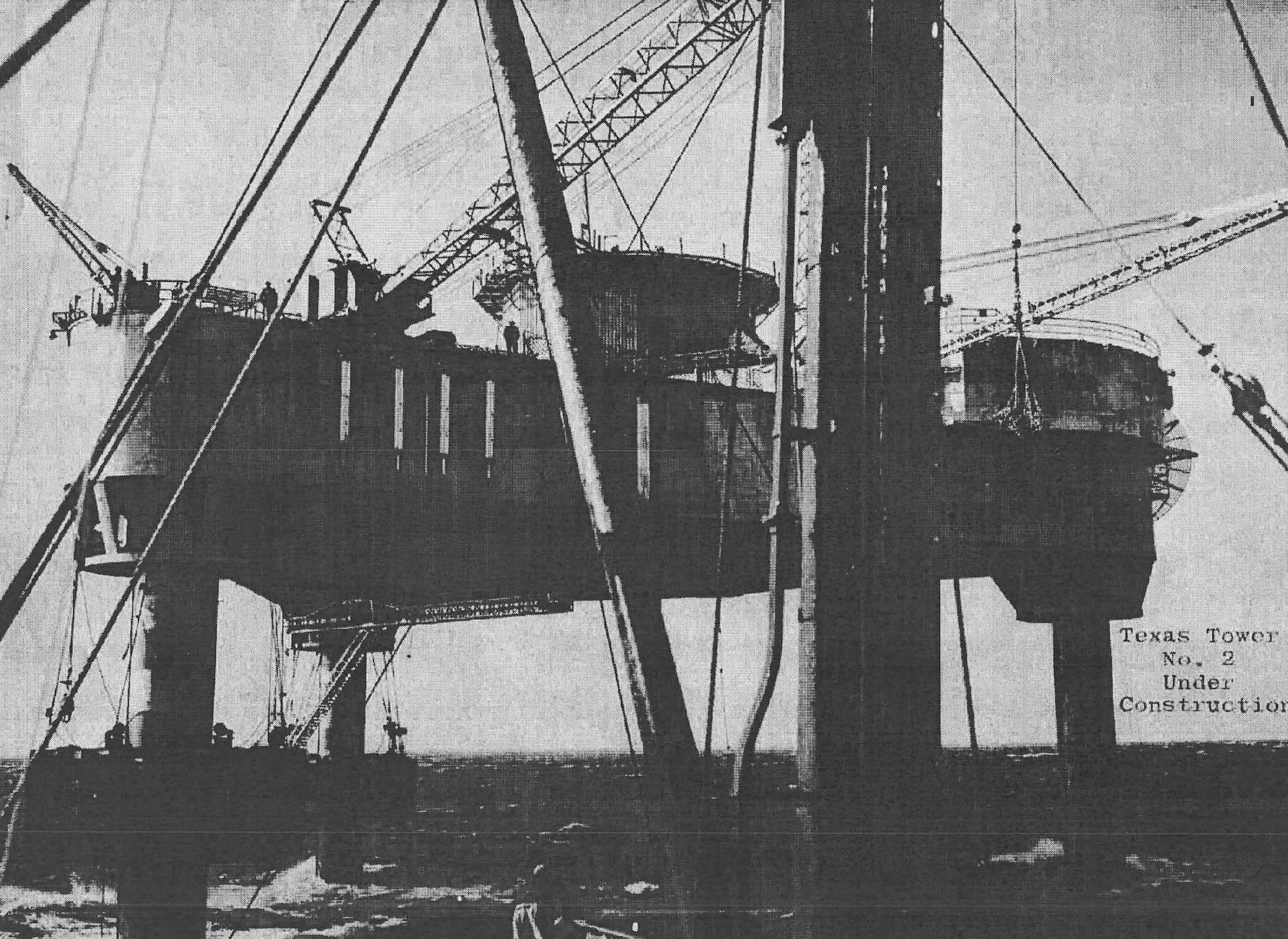
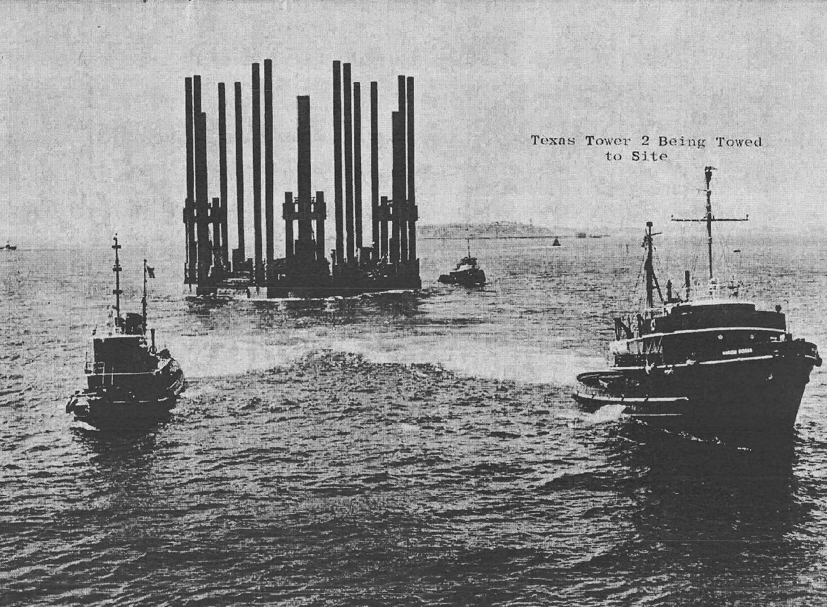
Bethlehem Steel fabricated the TT-2 platform at its Quincy, Massachusetts yard. By spring 1955 the large triangular hull-like structure was substantially complete. The Air Force history records a launch on May 20, while the construction narrative describes continuing fitting-out into June. Launch, completion of shore work, towing readiness, arrival on the shoal, emplacement, and beneficial occupancy were separate events, which explains why summaries sometimes use different construction dates.
The Raymond Concrete Pile Company and DeLong Corporation joint venture held responsibility for transporting and erecting the platform. The tow departed for Georges Shoal on July 12, 1955 and reached the site within approximately two days. Temporary legs were lowered to the shoal, the platform was jacked above the water, and the permanent caissons were prepared and installed. The procedure transformed a floating fabricated structure into a fixed station standing high above a dangerous shallow bank.
Emplacement demanded unusual offshore construction methods. Crews had to position the platform accurately, stabilize it on temporary supports, set long caissons into an irregular seabed, complete structural connections, add concrete and internal tubes, and finish utilities while exposed to fog, currents, swell, and rapidly changing weather. The project was both a building job and a marine operation. Delays or faults that would be manageable ashore carried greater consequences at a site more than a hundred miles from the principal support base.
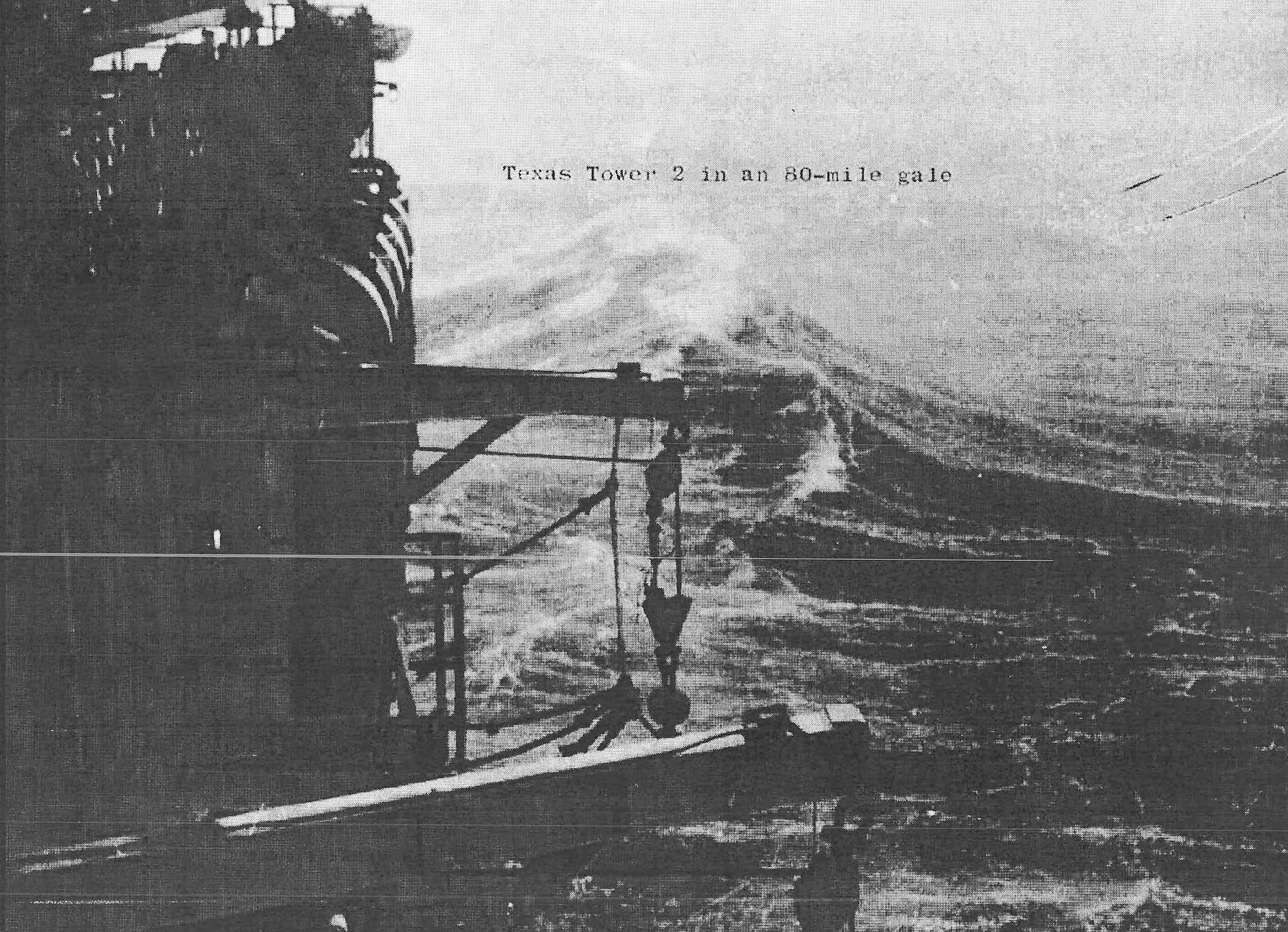
A severe storm in November 1955 struck while TT-2 remained under construction and demonstrated the force of the environment before the station was fully accepted. The event became part of the tower's institutional memory and reinforced the need for conservative weather decisions, strong mooring and support arrangements, and emergency reserves. TT-2 nevertheless reached a condition suitable for Air Force beneficial occupancy on December 2, 1955. Final technical installation and operational development continued after that date.
Radar, Data, and Communications Systems
The original radar suite consisted of an AN/FPS-3A long-range search radar and two AN/FPS-6 height finders. The search set supplied azimuth and range, while the two height finders provided altitude information needed for identification and interceptor control. Air Defense Command's consolidated data shows the search-radar sequence as AN/FPS-3A in 1956, AN/FPS-3 in 1958, AN/FPS-20 in 1959, and AN/FPS-67 in 1961. The removed-equipment sequence mirrors those changes, and the station closed with one AN/FPS-67 and two AN/FPS-6 sets.
Different sources use AN/FPS-20 and AN/FPS-20A for the intermediate search radar. This record preserves the command table's AN/FPS-20 designation while noting that the detailed historical narrative and later unit summaries describe the converted set as AN/FPS-20A. The distinction reflects configuration and reporting practice rather than proof of separate towers or simultaneous primary search sets. A planned AN/FPS-27 modernization appears in later secondary site histories, but no evidence was found that the set became operational on TT-2 before closure.
The tower also required equipment that did not appear in the short radar table. AN/GPA-37 processing and display equipment supported weapons-control functions. Mark X identification equipment and later associated interrogator equipment helped distinguish participating friendly aircraft. AN/FST-2 family data-transmission equipment supported automated reporting to SAGE. Navigation and landing aids assisted aircraft, while radio, interphone, public-address, teletype, and cryptographic systems connected operations, support functions, and the crew.
The AN/FRC-56 tropospheric-scatter link was the tower's principal long-distance shore connection. Three vertically mounted parabolic antennas approximately 28 feet in diameter were installed along the platform edge. Two could transmit while all three contributed to reception. By scattering UHF energy through the lower atmosphere, the link carried voice and data across a distance that would otherwise have required relay sites, and it supported both manual operations and later SAGE reporting.
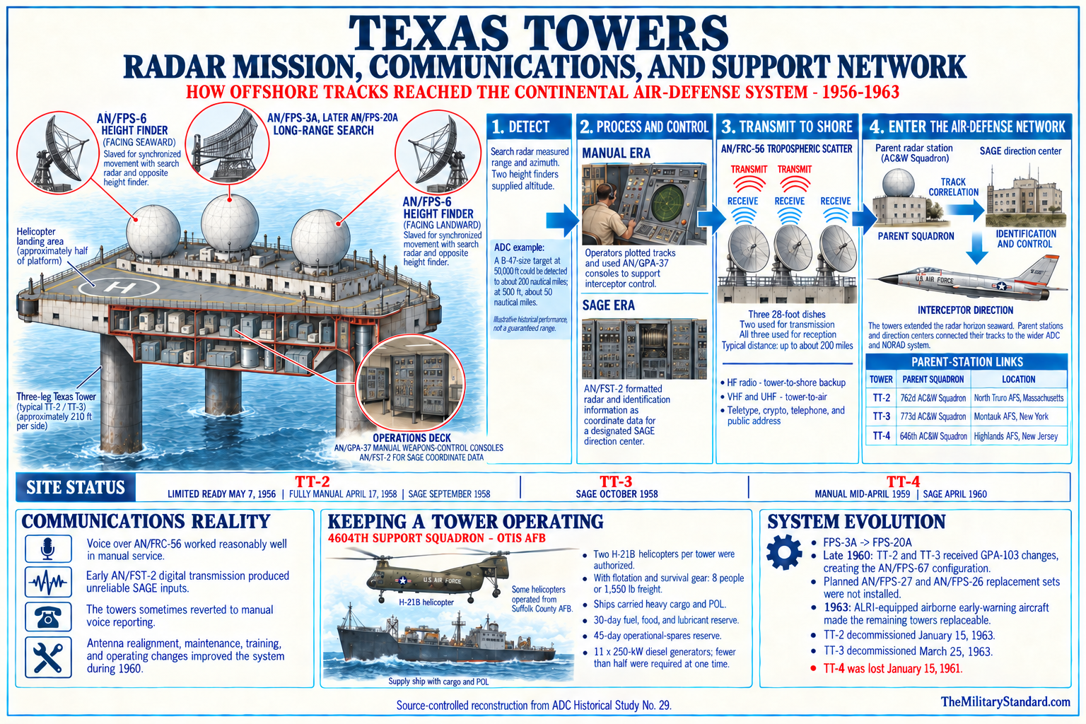
Conventional high-frequency circuits provided backup tower-to-shore communication, while UHF and VHF radios served tower-to-air traffic. Reliable communication was inseparable from radar performance because a track that remained on an offshore scope could not warn or control the continental defense system. The tower's communications complex therefore converted local detection into military value. It also allowed weather reports, logistics coordination, medical advice, command traffic, and crew contact with shore.
Electrical generation was a continuous industrial mission. Eleven 250-kilowatt diesel generators were installed, with fewer than half normally needed at one time to carry the load. The excess allowed maintenance and failure tolerance while radars, communications, lighting, ventilation, water production, galley, and living systems operated around the clock. Air conditioning was essential for electronic reliability and human habitability, not a comfort accessory, because enclosed radar and communications spaces generated substantial heat.
Operations and Sage Integration
On May 7, 1956, TT-2 achieved limited operational readiness as an aircraft control and warning station. Air Defense Command's historical table rounds that milestone to manual operations in May 1956. Crews used the radar picture locally, reported tracks to shore, and learned the station's electronic and environmental behavior while equipment and procedures matured. The station did not suddenly become complete on one day; readiness developed through installation, calibration, testing, training, communications validation, and correction of deficiencies.
Texas Tower No. 2 became fully operational in the manual system on April 17, 1958. Manual operations required people to interpret returns, correlate height and identity information, maintain plots, communicate tracks, and support ground-controlled interception without depending entirely on the automated digital network. This capability remained important even after SAGE because automation could fail and the tower still had to produce a coherent local air picture. The remote crew therefore combined radar maintenance, surveillance, reporting, and weapons-control skills.
The tower became operational as a SAGE site in September 1958. SAGE digitized radar information and transmitted it to a direction center, where computers and controllers combined reports from multiple stations into a regional air picture and directed interceptors. TT-2's value was not simply its isolated range. It was the seaward geometry that its data added to a network of coastal radars, airborne early-warning aircraft, picket ships, direction centers, communications systems, and fighter bases.
At high altitude, the original radar installation could detect a target comparable to a B-47 at a reported distance approaching 200 nautical miles under favorable conditions. At approximately 500 feet, line-of-sight geometry reduced detection distance to roughly 50 nautical miles. Those figures are capability illustrations from the historical program narrative rather than guaranteed performance for every target and weather condition. They explain both why the tower offered useful warning and why fixed offshore radar could not eliminate the low-altitude gap by itself.
Summer temperature inversions sometimes bent or trapped radar energy, producing coverage loss, anomalous propagation, and persistent returns that obscured or distorted scopes. Electronic equipment could also interfere with other systems in the dense platform environment. These were not unusual footnotes but operational constraints that crews had to recognize and manage. The tower was a sophisticated radar station placed in a difficult propagation environment with no room to separate major emitters by miles, as could be done at some land installations.
Organization, Command, and Support
The 762d Aircraft Control and Warning Squadron at North Truro Air Force Station supplied the original operational parentage. TT-2 functioned as its offshore annex, with radar operators, controllers, technicians, and supporting airmen detached to the tower. When Air Defense Command redesignated many units for SAGE, the parent became the 762d Radar Squadron (SAGE). The relationship tied the seaward station to an established shore radar organization while preserving TT-2 as a distinct staffed installation.
Support responsibility formally shifted from the 762d to the new 4604th Aircraft Control and Warning Squadron (Texas Towers) at Otis Air Force Base on October 8, 1956. The support squadron itself had been activated on September 28, and on December 31 it was redesignated the 4604th Support Squadron (Texas Towers). These dates describe organization and transfer of support, not a change in the physical tower. The 762d continued the operational radar relationship while the 4604th specialized in the unusual logistics shared by the offshore stations.
Higher command assignments also changed as Air Defense Command reorganized. Unit summaries associate TT-2 with the 4704th Defense Wing in May 1956, the 4622d Air Defense Wing from October 18, 1956, and the Boston Air Defense Sector from January 8, 1957 until inactivation. The Boston sector relationship became especially important when SAGE connected the tower to automated direction-center operations. Such assignment changes should be understood as shifts in command architecture rather than repeated openings or closures.
The planned complement was initially smaller than actual operating experience required. By 1957 a typical Texas Tower crew was reported as six officers and forty-eight airmen, although numbers varied with maintenance, construction, weather, training, and mission demands. Civilian contractor personnel could also be present for specialized work. The crew had to cover continuous watches, electronic maintenance, power generation, utilities, food service, medical response, administration, communications, weather observation, firefighting, security, and emergency preparation.
Logistics, Transportation, and Life Aboard
Helicopters provided the fastest routine connection to shore. The Air Force authorized two H-21B helicopters per tower, with four based at Otis Air Force Base and two at Suffolk County Air Force Base for the Texas Tower system. Flotation and survival equipment reduced the H-21B's theoretical load to about eight passengers or 1,550 pounds of freight. Weather, visibility, aircraft availability, deck conditions, weight, and fuel imposed additional practical limits.
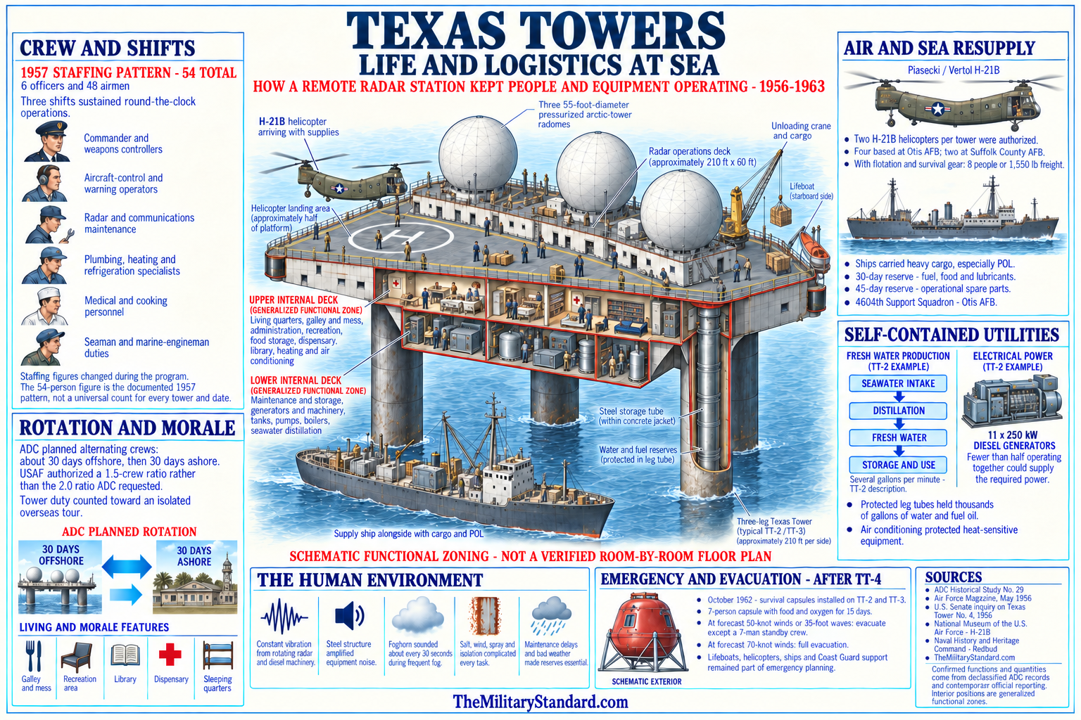
Surface vessels carried heavy cargo, bulk fuel, lubricants, and supplies that helicopters could not move efficiently. Transfer from a moving ship to a fixed platform in Atlantic swell required cranes, rigging, schedules, and crews trained for marine handling. A normal resupply mission could become hazardous when wind or sea state increased. The tower therefore carried at least a 30-day reserve of fuel, food, and lubricants and approximately 45 days of spare parts for operational equipment.
The helipad gave the station an aviation facility but not the flexibility of an airfield. A helicopter could land only when visibility, wind, deck condition, and aircraft limits permitted. Fog was common on Georges Bank, and a foghorn sounded at regular intervals, adding another vibration and noise source. Medical evacuation, personnel rotation, mail, fresh food, and technical assistance could all be delayed, so tower personnel lived with a degree of isolation uncommon at continental radar sites.
Daily life combined military routine with the physical sensations of a steel structure at sea. Rotating antennas, diesel engines, pumps, ventilation machinery, waves, and wind kept the platform in near-continuous vibration. The legs transmitted and amplified underwater and structural sounds, making the tower behave like a large resonating instrument. Crews learned which motions and noises were ordinary, a skill that helped them work but could also make judgments about changing structural behavior psychologically difficult.
Living areas included bunks, mess facilities, recreation space, a dispensary, and a library, but privacy and escape from machinery were limited. Watch schedules continued through nights, weekends, storms, and holidays because the air-defense picture could not be suspended. Contemporary newsletters and later recollections record both hardship and strong community: card games, films, amateur radio, shared meals, maintenance work, inspections, jokes, and anticipation of the next rotation all formed part of tower culture.
Weather shaped almost every activity. Fog interfered with flight operations and visual navigation, storms restricted ship transfers, salt attacked metal and electrical connections, and winter seas produced vibration and concern that could not be replicated in shore training. Emergency procedures had to address fire, power failure, medical injury, failed water production, helicopter accident, loss of communications, and structural danger. Readiness depended on keeping both the radar mission and the artificial habitat functioning.
Structural Experience and Safety
TT-2's relatively shallow-water design proved more stable than the long-legged TT-4, but it was never free of concern. The platform experienced constant motion and fatigue-producing vibration, and the shoal environment could scour material around foundations. Maintenance and inspection therefore formed an ongoing part of safe operation. The experience gained from TT-2 influenced later towers, which received design changes including longer legs and greater fuel capacity for their deeper sites.
The January 15, 1961 collapse of TT-4 changed the risk calculation for every remaining offshore station. TT-4 had suffered known brace and connection failures and severe hurricane damage before a winter storm destroyed it with twenty-eight military and civilian personnel aboard. TT-2 did not share every structural characteristic or failure sequence, and there is no basis to say it was about to collapse in the same way. The disaster nevertheless made the consequences of divided responsibility and delayed evacuation impossible to ignore.
After TT-4, inspections, weather evacuation policy, structural review, and the cost of repair received greater scrutiny. By late 1962 TT-2 was sufficiently threatened during a storm that the destroyer leader USS Willis A. Lee took off its crew in a rescue operation. The event confirmed that even the oldest and shallowest tower could require naval assistance. Safety was no longer weighed only against radar availability; it was compared with alternative surveillance systems and the acceptable risk of maintaining dozens of people offshore.
Role in the Wider Military Network
Texas Tower No. 2 filled a specific geometric gap between continental radar and the open Atlantic. Its search and height data extended the northeastern warning line beyond Cape Cod and gave commanders more time to identify tracks, evaluate threat, alert fighter units, and prepare interception. The station did not defend an area by itself. It made the larger defense system more effective by contributing earlier and differently positioned observations.
North Truro Air Force Station provided the closest operational parent and a coastal radar picture that overlapped the tower's coverage. Otis Air Force Base supplied the specialized support squadron, helicopters, maintenance coordination, stores, and administrative infrastructure. The Boston Air Defense Sector and its SAGE direction center converted the tower's reports into a regional picture. Fighter-interceptor bases provided the aircraft that could act on that information, while communications networks carried commands and track data.
The tower also operated alongside Navy radar picket ships and Air Force airborne early-warning aircraft. Surface pickets could move and airborne platforms could see low-flying aircraft farther beyond their local horizon, but both demanded crews, fuel, maintenance, and recurring patrols. A fixed tower offered constant presence and a stable equipment platform, yet could not reposition and remained exposed to weather and structural aging. The offshore defense system therefore combined complementary methods rather than relying on one perfect solution.
SAGE increased the importance of consistent track reporting and reliable data transmission. AN/FST-2 family equipment and the tropospheric-scatter link allowed TT-2 information to enter an automated network in which computers correlated radar reports and supported weapons assignment. The tower's radars remained local sensors, but its operational effect became regional. This distinction explains why communications failure could reduce military value even when the antennas and scopes still worked.
The later Airborne Long Range Input concept made the same network function possible from modified EC-121 airborne early-warning aircraft. ALRI receivers ashore could send airborne radar data into SAGE, combining mobility, broader low-altitude coverage, and freedom from a fixed ocean foundation. As ALRI approached deployment, the argument for maintaining expensive and risky towers weakened. Texas Tower No. 2 thus marked one stage in a continuing effort to push sensors outward, not the final form of seaward warning.
Decommissioning and Demolition
On January 2, 1963, the Joint Chiefs of Staff directed immediate inactivation of TT-2 and reduction of TT-3 to a seven-person security crew until ALRI became operational. The Air Force publicly announced the Texas Tower decision on January 8. Air Defense Command decommissioned TT-2 on January 15, exactly two years after TT-4 collapsed. Radar operations, unit manning, equipment removal, property accountability, and demolition then proceeded as distinct closeout tasks.
The decision rested on several overlapping factors. Seabed scour and structural concerns required continuing investigation and potentially expensive repair. Severe weather had repeatedly forced the Air Force to consider or execute evacuation. TT-4 had demonstrated the human consequences of misjudging risk. At the same time, changing emphasis from bomber defense toward missile warning and the arrival of ALRI reduced the unique operational value of a fixed offshore station.
Texas Tower No. 3 ended radar operations on March 25, 1963, leaving no operating Texas Tower. The sequence matters because some summaries describe 1963 as a single program closure. TT-2 closed first under the immediate order, TT-3 followed after a short caretaker period, and physical removal came later. This record uses January 15 as TT-2's military inactivation date and September 1963 as its demolition period.
The Air Force removed usable radar, communications, and support equipment before demolition. In September 1963 explosives were used to bring down the remaining structure. An official Air Force annual report states that TT-2 was demolished that month and gives the combined construction cost of the three towers as approximately $12.3 million in its accounting context. Other program histories use approximately $13 million for each equipped tower and about $1.5 million in annual operating expense, showing that cost figures differ according to what was included.
The structure sank during the demolition and dismantling operation. Current NOAA navigation guidance identifies the remains as a submerged obstruction on Georges Shoal. The wreck is not an abandoned land parcel that could be redeveloped, and no public evidence reviewed establishes a modern Air Force custodial program, a FUDS response project, or a public access regime. Mariners must rely on current charts and notices, and diving claims in secondary sources do not constitute access or safety authorization.
Current Condition, Environment, and Preservation
NOAA's current Coast Pilot is the clearest authoritative statement of present physical status. It identifies a submerged obstruction, the remains of an old Texas tower, at 41 degrees 41.8 minutes north and 67 degrees 46.4 minutes west. The same publication describes Georges Shoal as a roughly 16-mile ridge with shallow depths and warns of breaking seas, strong and variable currents, tide rips, swirls, overfalls, and numerous dangerous spots. The wreck sits in an already hazardous marine environment.
The submerged steel, concrete, cables, and former machinery constitute a Cold War archaeological resource as well as a navigation obstruction. No current National Register listing, federal preservation management plan, archaeological survey, or protected memorial designation specific to TT-2 was located. That absence does not erase historical significance. It means that condition, integrity, ownership, biological colonization, debris spread, and preservation status remain unresolved without a modern seabed survey and legal review.
No tower-specific environmental remediation record was located in the FUDS, Defense Environmental Restoration Program, or other public sources. The station stored large quantities of diesel fuel and lubricants and contained electrical and electronic equipment typical of its era, but this history does not infer a release, remaining contaminant, or cleanup obligation without evidence. Demolition and decades of marine exposure make environmental questions legitimate research subjects, not established findings.
Georges Bank is a major fishing and ecological area, and contemporary navigation guidance also addresses endangered North Atlantic right whales in the region. Those modern environmental conditions are not part of the Air Force mission, but they affect any present investigation or visitation. Survey, salvage, diving, anchoring, or artifact removal may implicate navigation, fisheries, offshore-resource, environmental, safety, and historic-preservation rules. No coordinate in this history is permission to approach or disturb the wreck.
Historical Conflicts and Evidence Limits
The opening date is the most common source of confusion. December 2, 1955 was activation and beneficial occupancy, May 7, 1956 was limited operational readiness, May 1956 is the command table's manual-operations entry, April 17, 1958 was full manual operation, and September 1958 was SAGE operational status. A statement that the tower opened only in 1958 erases more than two years of development and limited operations. A statement that it was fully operational in 1955 is equally misleading.
Location descriptions also require qualification. Historical sources use George's Shoal, Georges Shoal, Georges Bank, New York, Massachusetts, 110 miles east of Cape Cod, and 137 miles east of Cape Cod. These variations reflect spelling, catalog practice, regional association, and measurement, not multiple TT-2 structures. The modern NOAA wreck coordinate differs from the rounded Air Force station point, and neither should be converted into a falsely exact legal boundary.
Equipment sources agree on two AN/FPS-6 height finders and on the general search-radar modernization path, but nomenclature varies between AN/FPS-20 and AN/FPS-20A. The Air Defense Command table is treated as controlling for the sequence, with the detailed history used to explain the A-model description. Secondary lists name additional communications, processing, navigation, and identification sets, but not every configuration date is documented.
Staffing, cost, distance, and dimensions vary according to date and definition. Six officers and forty-eight airmen describes a typical mature crew, not a guaranteed daily strength. Half an acre describes platform surface, not a landholding or seabed estate. Program cost may refer to a structure, an equipped tower, or all three platforms. Distances depend on the Cape Cod reference point and whether measured directly or by operating route.
No complete day-by-day operations log, roster, commander list, sortie record, track count, interception total, accident register, maintenance ledger, equipment serial list, construction drawing set, demolition report, seabed title opinion, or modern archaeological survey was recovered in the public research. The Air Force Historical Research Agency and National Archives likely hold additional records, including ADC Historical Study No. 29 and unit histories.
Chronology
- August 1, 1952 MIT Lincoln Laboratory outlined a fixed offshore radar-platform concept for extending warning coverage seaward.
- Autumn 1953 The Air Force authorized a five-tower program consisting of TT-1 through TT-5.
- Fiscal years 1954 and 1955 The Air Force programmed funds for survey, engineering, construction, radar, and support development.
- October 1954 The Navy-managed feasibility study for the five proposed sites was completed.
- December 1954 The Bureau of Yards and Docks awarded work for tower design and specifications.
- Spring 1955 Bethlehem Steel substantially completed the TT-2 platform at Quincy, Massachusetts.
- May 20, 1955 The first Texas Tower platform was launched according to the official Air Force program history.
- June 1955 Fitting-out and preparation for the sea tow continued.
- July 12, 1955 The Raymond and DeLong construction team began towing TT-2 from Quincy toward Georges Shoal.
- About July 14, 1955 The platform reached the Georges Shoal construction site.
- July through November 1955 Temporary supports, permanent caissons, concrete, utilities, superstructure, and equipment were installed offshore.
- November 1955 A severe storm struck the station during the construction and fitting-out period.
- December 2, 1955 Air Defense Command accepted beneficial occupancy and activated the TT-2 station organization.
- 1956 The initial AN/FPS-3A search radar and two AN/FPS-6 height finders entered the documented equipment record.
- May 7, 1956 TT-2 achieved limited operational readiness as an aircraft control and warning station.
- May 1956 The Air Defense Command consolidated table records the beginning of manual operations.
- July 1956 Air Defense Command revised the operating plan governing TT-2 and its parent station.
- September 28, 1956 The 4604th Aircraft Control and Warning Squadron (Texas Towers) activated at Otis Air Force Base.
- October 8, 1956 Support responsibility transferred from the 762d Aircraft Control and Warning Squadron at North Truro to the 4604th at Otis.
- October 18, 1956 Higher assignment shifted to the 4622d Air Defense Wing according to later unit summaries.
- Late 1956 Air Defense Command agreed to eliminate unbuilt TT-1 and TT-5 from the program because improved coastal coverage reduced their expected value.
- December 31, 1956 The 4604th was redesignated the 4604th Support Squadron (Texas Towers).
- January 8, 1957 The Boston Air Defense Sector became the higher operational assignment identified for the tower.
- 1957 A mature Texas Tower crew was normally reported as six officers and forty-eight airmen.
- 1958 The AN/FPS-3A was replaced or redesignated in the documented sequence by an AN/FPS-3.
- April 17, 1958 TT-2 became fully operational in the manual air-defense system.
- September 1958 TT-2 became operational as a SAGE radar station.
- 1959 The search radar changed from AN/FPS-3 to AN/FPS-20, described as AN/FPS-20A in the detailed historical narrative.
- 1961 The AN/FPS-20 family set was replaced by an AN/FPS-67 search radar.
- January 15, 1961 Texas Tower No. 4 collapsed, fundamentally changing safety review and public understanding of the remaining towers.
- 1961 through 1962 TT-2 continued SAGE operations with one AN/FPS-67 and two AN/FPS-6 height finders.
- Autumn 1962 USS Willis A. Lee removed the crew of storm-endangered TT-2 in a Navy rescue operation.
- January 2, 1963 The Joint Chiefs of Staff directed immediate inactivation of TT-2 and caretaker reduction of TT-3 pending ALRI.
- January 8, 1963 The Air Force announced its decision to decommission the Texas Towers.
- January 15, 1963 Texas Tower No. 2 was decommissioned and its radar mission ended.
- March 1963 The first Airborne Long Range Input station entered the SAGE network.
- March 25, 1963 Texas Tower No. 3 was decommissioned, ending operation of the last Texas Tower.
- March through August 1963 Additional ALRI stations became operational and replaced part of the seaward-input function.
- September 1963 Texas Tower No. 2 was demolished with explosives after removal of reusable equipment.
- September 1963 The dismantled tower sank, leaving the remains now charted on Georges Shoal.
- 1964 Air Defense Command's dedicated Texas Towers historical study closed its main narrative period.
- March 1965 The command issued ADC Historical Study No. 29, A History of Texas Towers in Air Defense, 1952-1964.
- 1997 The Air Force-sponsored Searching the Skies history placed Texas Towers in the documented national Cold War radar network.
- 2014 NOAA expanded public access to wreck and obstruction information while cautioning that older positions can differ from current charted features.
- 2026 The current U.S. Coast Pilot continued to identify the remains of an old Texas tower as a submerged obstruction at 41 degrees 41.8 minutes north, 67 degrees 46.4 minutes west.
Information sources (36)
- PDFADC Historical Data, 1946-1973. (17.6 MB)
Aerospace Defense Command, historical data compilation, especially Section III and the Radar Program, Texas Towers, 1956-1963 table.
- PDFA History of Texas Towers in Air Defense, 1952-1964, ADC Historical Study No. 29. Aerospace Defense Command Office of Information, Historical Division, March 1965
Core official program history for requirement, design, construction, equipment, organization, life, operations, support, and closure.
- PDFEstablishing Independence and operational Air Force history. Air Force History and Museums Program
Official narrative for the five-site plan, Lincoln Laboratory concept, Navy engineering role, TT-2 construction, platform arrangement, and program development.
- PDFA Handbook of Aerospace Defense Organization, 1946-1980. Office of History, Aerospace Defense Center
Official reference for Air Defense Command organizations, sectors, units, and redesignations.
- PDF762 Radar Squadron (SAGE) lineage and station compilation
Air Force unit-history source for TT-2 coordinates, parent relationship, call sign, equipment, operational milestones, logistics, and decommissioning.
- WEBSearching the Skies: The Legacy of the United States Cold War Defense Radar Program. David F. Winkler, prepared for Headquarters Air Combat Command, 1997
Official Air Force-sponsored context for the continental radar network and Texas Towers.
- WEBAir Defense Command fact sheet. Department of the Air Force History and Museums Program
Official command mission, lineage, and continental air-defense context.
- WEBSAGE: Semi-Automatic Ground Environment Air Defense System. MIT Lincoln Laboratory
Official laboratory history of the automated network into which TT-2 reported beginning in September 1958.
- WEBHistorical Review of North American Aerospace Defense, 1946-1970. NORAD historical study
Official source for the seaward-extension concept, completed towers, and early operations.
- WEBAir Defense Command and Antibomber Defense, 1946-1972, ADC Historical Study No. 39
Official source for decommissioning TT-2 and TT-3 and introducing ALRI to SAGE.
- PDFNORAD and CONAD Historical Summary, January-June 1963
Official command history for the January 2 directive, January 15 TT-2 inactivation, TT-3 caretaker phase, reasons for closure, and ALRI transition.
- PDFNORAD and CONAD History, 1956-1957
Official command history and reference notes for early TT-2 operations and seaward radar and communications planning.
- PDFA Chronology of Air Defense, 1914-1972, ADC Historical Study No. 19
Official chronology for the January 8, 1963 announcement, January 15 TT-2 decommissioning, March 25 TT-3 decommissioning, and ALRI sequence.
- PDFAnnual Report of the Secretary of the Air Force for fiscal year 1963
Official source stating that TT-2 was demolished with explosives in September 1963 and describing cost and strategic rationale.
- PDFU.S. Coast Pilot 1, Chapter 3. NOAA Office of Coast Survey, current edition
Authoritative navigation source for Georges Bank, Georges Shoal, hazards, and the charted Texas Tower remains at 41 degrees 41.8 minutes north, 67 degrees 46.4 minutes west.
- WEBWrecks and Obstructions. NOAA Office of Coast Survey
Current official explanation that ENC Direct now provides the latest charted wreck and obstruction information and that the older AWOIS service is retired.
- WEBCoast Survey Improves Access to Data on Thousands of Wrecks and Obstructions. NOAA, July 8, 2014
Official explanation of wreck-position limitations and the relationship between historical AWOIS records and charted positions.
- WEBDictionary of American Naval Fighting Ships, USS Willis A. Lee. Naval History and Heritage Command
Official record of the ship's rescue of the storm-endangered TT-2 crew.
- WEBAir Defense, Air & Space Forces Magazine, December 1999
Air Force Association overview confirming three completed towers, TT-2 operation beginning in December 1955, and final closure in 1963.
- WEBGlory, Air & Space Forces Magazine, September 1958
Contemporary account of the three-tower system, offshore distance, helicopter support, and service conditions.
- WEBThe Construction, The Texas Towers Association
Detailed reproduction and synthesis of the official program history for fabrication, emplacement, decks, caissons, radar, communications, power, logistics, readiness, and later towers.
- WEBThe Texas Towers Association home page
Veterans and preservation organization with tower histories, rosters, photographs, memories, newsletters, and memorial context.
- WEBTexas Towers index and ADC Historical Study No. 29 resource page. Radomes, Inc
Access route for site pages, photographs, films, newsletters, November 1955 storm material, and the official historical study.
- WEBTexas Tower No. 2 site record. Radomes, Inc
Secondary site reference for equipment sequence, parent relationships, photographs, veterans' material, and research leads.
- WEBTexas Tower No. 2 notes and recollections. Radomes, Inc
Secondary collection for H-21 operations, tower service, and veterans' accounts.
- WEB26. Texas Tower No. 2 topics and newsletters. Radomes, Inc
Primary contemporary unit-newspaper reproductions and supporting documents for station life and activities.
- WEBTexas Tower 2. FortWiki
Secondary synthesis used only for cross-checking equipment, coordinates, units, and disposition against official material.
- WEBAnnual Reports of the Secretary of the Air Force collection. Library of Congress
Archival route for official annual reports surrounding tower operation and demolition.
- PDFGuide to Air Force Historical Literature, 1943-1983
Department of the Air Force History and Museums Program. Official bibliography identifying ADC Historical Study No. 29 and related command studies.
- PDFU.S. Air Force Bases history. Air Force History and Museums Program
Official contextual reference identifying the three artificial offshore platforms in the Air Defense Command network.
- WEBContinental Air Defense historical study, volume 2. U.S. Army Center of Military History
Official joint air-defense context noting TT-2 beneficial occupancy in December 1955 and the tower's limited ground-controlled-interception role.
- WEBInquiry into the Collapse of Texas Tower No. 4. U.S. Senate Committee on Armed Services, 1961
Official record for program responsibilities, engineering history, risk, inspections, and the disaster that shaped review of TT-2 and TT-3.
- WEBInquiry into the Collapse of Texas Tower No. 4, digitized hearing
Internet Archive copy of the official Senate record with drawings, testimony, chronology, and exhibits.
- PDFHistory of Oceanography in the Offshore Waters of the United States. National Marine Fisheries Service
Official scientific-history source noting oceanographic observations at Texas Tower No. 2 and the wider Georges Bank research setting.
- WEBHistorical Map and Chart Collection. NOAA Office of Coast Survey
Official research route for chart editions showing Georges Shoal and later wreck or obstruction markings.
- WEBHydrographic Survey Data. NOAA Office of Coast Survey
Official access route for survey records and data relevant to the wreck area and charting history.