
AN/FPS-8 Medium-Range Search Radar
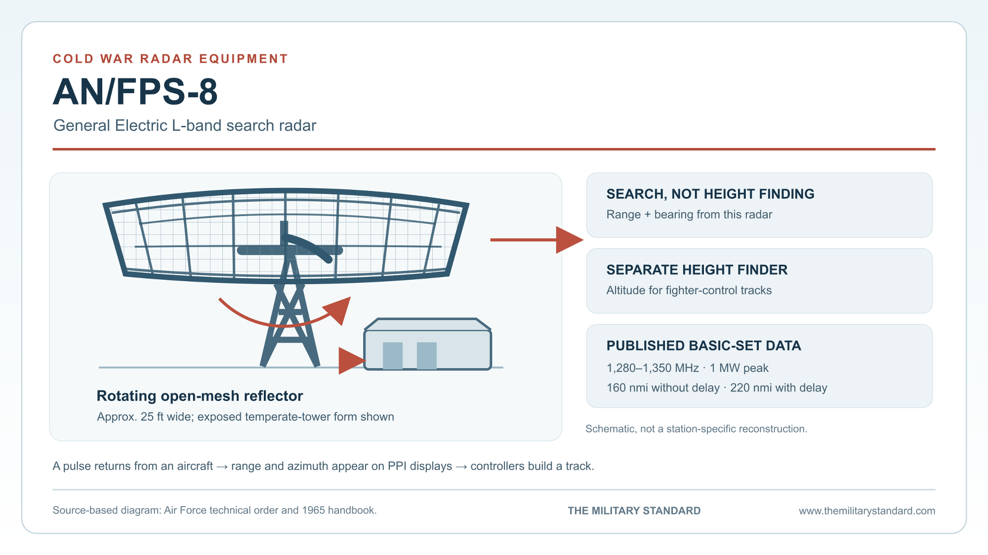
A wide, rotating antenna helped Cold War radar stations find approaching aircraft. The AN/FPS-8 supplied range and bearing for air-defense controllers, while separate height finders supplied altitude.
- Role
- Fixed, air-transportable L-band air-search and early-warning radar.
- Manufacturer
- General Electric, Syracuse, New York.
- Basic-set frequency
- 1,280 to 1,350 MHz in the Air Force technical order.
- Peak pulse power
- 1 megawatt.
- Published range settings
- 160 nautical miles without delay; 220 nautical miles with delay.
- Production
- More than 200 units, 1954 to 1958.
Overview
The General Electric AN/FPS-8 was a fixed, air-transportable L-band search radar built for Cold War aircraft warning and ground-controlled interception. Its broad, rotating antenna supplied an approaching aircraft's bearing and distance. A separate height-finding set supplied altitude when controllers needed a three-dimensional track to direct fighters. The Air Force's 1965 equipment handbook explicitly provides connections for such a height finder; the FPS-8 itself was not one. [1] [2] [3]
More than 200 FPS-8 units were produced between 1954 and 1958 according to the Air Force's history of the defense-radar program. They appeared at permanent and mobile-program radar stations, in Alaska, and in related mobile and later modified configurations. At some sites an AN/FPS-8 worked alongside an older search set for a time; at others it became the principal search radar before a later upgrade. Those differing installation histories explain why the equipment cannot be assigned one universal service date or replacement sequence. [3] [4] [5]
The Warning Mission
Early warning depended on both detecting an aircraft and getting its position to controllers quickly enough to act. A search set swept the surrounding airspace and plotted echoes by range and azimuth. Controllers compared repeated plots, identified tracks and, when required, directed interceptors toward them. Height finding was a distinct measurement. The FPS-8 handbook describes the radar as an early-warning set with moving-target indication and states that it could support a separate height finder in a ground-controlled-intercept installation. [1] [2]
The FPS-8 arrived during a period when Air Defense Command was expanding its permanent and mobile radar network. General Electric made the equipment in Syracuse, New York. Its combination of a transportable equipment package, broad azimuth scan and fixed-station operating arrangement let the Air Force place the same basic search capability at very different sites. Its published range settings were substantial for the 1950s, but mission planners still had to account for terrain and the earth's curvature when siting a radar tower. [1] [2] [3]
Air Defense Command's own radar-program study captures the uncertainty surrounding the new set. In 1955, planners proposed the FPS-8 for three Phase II mobile sites. An Air Proving Ground Command suitability test completed that August judged it superior to the older AN/FPS-3. Air Defense Command's shorter comparison reached a more qualified conclusion: the FPS-8 appeared better than the basic FPS-3 but not as capable as an FPS-3 improved with the AN/GPA-27 kit. The service therefore did not make the FPS-8 its sole standard search radar. It entered a network in which different generations of sensors overlapped. [12]
How the Set Worked
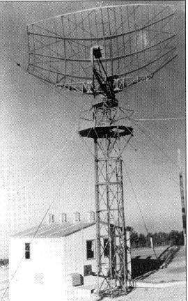
The antenna group was an open-mesh, curved reflector approximately 25 feet wide. It rotated through a full circle at up to 10 revolutions per minute or could search a selected sector. The transmitter generated short L-band pulses. The time between each pulse and its echo established range, while the antenna position established azimuth. Operators viewed returns on plan-position indicators, which presented the surrounding area as a map-like circular display. The handbook lists two to six 12-inch PPI displays and a separate five-inch A-scope. [1] [2]
The technical order describes the FPS-8's overall vertical radiation coverage as about 30 degrees, with the lower limit adjustable near the horizon. That coverage helped the search radar see aircraft at different elevations, but it did not make the set a precision height finder. A separate nodding or otherwise dedicated height-finding radar could provide the altitude information needed for a fighter intercept. The distinction is visible in the 1965 handbook's provision for a height-finder power and trigger connection. [1] [2]
Ground reflections and fixed objects could obscure moving aircraft on a radar display. The FPS-8 used coherent-video-cancellation moving-target indication to reduce fixed clutter. The technical order describes MTI clutter reduction out to 150 nautical miles, interference blanking for as many as three nearby radar sets, and circuits to reduce noise and continuous-wave jamming effects. These were operating features of the search system, not a guarantee that every aircraft could be detected at its instrumented maximum range. [1] [2]
Technical Characteristics
The Air Force technical order and the 1965 equipment handbook give the operating frequency as 1,280 to 1,350 MHz, a nominal one-megawatt peak pulse, a three-microsecond pulse width and a pulse repetition rate of 360 per second. The handbook lists 160 nautical miles of range without delay and 220 nautical miles with delay. These are equipment settings or rated capabilities; actual detection varied with target size, altitude, terrain, propagation and operating conditions. [1] [2]
The handbook lists a 2.5-degree horizontal beam width, a nine-degree vertical beam width, half-degree azimuth accuracy and approximately half-mile range accuracy. The antenna group measured about 200 inches high by 300 inches wide by 72 inches deep, and weighed 2,429 pounds. The radar's electrical requirement was approximately 20 kilowatts at 120/208 volts, three-phase, 60 hertz. None of these figures describes the total personnel, power or physical acreage of a complete radar station. [2]
The stated range figures describe where the display could place an echo, not a promise that the radar could see every aircraft at those distances. A low-flying target might be hidden below the radar horizon or behind nearby terrain. At higher altitude, aircraft could be visible much farther away. That practical distinction mattered especially in Alaska, where a coastal or mountain station could face a very different horizon from a set with the same designation on flatter ground. Search-radar coverage, height-finder coverage and the communications route to a control center all shaped a station's real warning value. [1] [2] [6]
Buildings, Towers and Operators
The antenna could be mounted on a temperate tower or in an Arctic tower and protective radome. The handbook identifies the AB-397/FPS-8 temperate tower and AB-313/FPS-8 Arctic tower. It places the indicator and control equipment in an operations building and the power equipment in a separate power building. A field installation therefore involved more than the visible antenna: transmitter, receiver, modulator, power supply, displays and communications connections all had to operate together. [2]
An Air Force historical photograph shows an exposed FPS-8 reflector high on a lattice tower beside a low equipment building. Its broad horizontal shape is characteristic of a search antenna. Arctic installations could look different because the antenna was enclosed against wind and ice; a radome photograph by itself does not identify the radar model inside. The Air Force photograph reproduced with this history illustrates the equipment type, not a verified view of any one Alaska station. [2] [8]
At an operating station, a search contact was only the beginning of an interception. Plotters and controllers compared successive echoes, determined course and speed, and passed track information to the control organization. If a fighter was launched, a height finder and communications circuits helped guide it toward the target. The FPS-8 supplied the search picture for that chain, while its electrical connections let the radar work with other station equipment. In later years, some installations also adapted their azimuth information for the Semi-Automatic Ground Environment. The technical order lists an azimuth-pulse generator for FPS-8 installations affected by SAGE; it was not universal equipment on every set. [1] [2]
Alaska and the Northern Network
Alaska's Aircraft Control and Warning stations had to watch long approaches across remote territory and coastal waters. A declassified CONAD/NORAD history states that the 1957 modernization plan called for AN/FPS-8 sets at Unalakleet, Bethel. Its later summary counted three AN/FPS-8s in the operating Alaska network at the end of 1958. [4] [5]
At Kotzebue, the permanent station replaced its original lightweight search radar with an AN/FPS-8 and paired it with an AN/FPS-4 height finder. The state Aircraft Control and Warning history records a later AN/FPS-6 height finder in 1962 and an AN/FPS-20 search radar in 1963. The FPS-8 phase thus belonged to Kotzebue's transition from a temporary outpost to a permanent fighter-control installation; it did not continue unchanged through the site's later minimally attended radar era. [6]
At Campion Air Force Station, an AN/FPS-8 was added in 1955 during the station's ground-controlled-intercept years. Campion then received an AN/FPS-20 search-radar conversion and, later, AN/FPS-93A search and AN/FPS-90 height-finding equipment. These were successive changes in a single station's radar plant, as Alaska's warning network moved from manual plotting toward more capable sensors and data processing. [5] [6] [9]
Service Beyond Alaska
The FPS-8 spread across the continental radar network as well. The Air Force radar-program history records a 1955 FPS-8 installation at North Truro, Massachusetts, later converted to AN/GPS-3. Other station histories show the same changeover at North Bend, Oregon, and Naselle, Washington. These examples illustrate a family of related configurations rather than a universal requirement that every FPS-8 was redesignated GPS-3. [3] [10] [11]
Those coastal stations served a different geography from the Alaska outposts but the same basic warning mission. A rotating search antenna could supply repeated range-and-bearing plots over sea approaches, while separate height-finding sets supported intercept control. Such installations also show why a radar-equipment history and an installation history need different timelines: the same FPS-8 design could be newly installed at one station while another station was already modifying its equipment or preparing for a successor. [2] [3] [10] [11]
The Hawaii Air National Guard's historical annual-report material provides a useful operational example. It explicitly calls the AN/FPS-8 a search radar used by its 169th and 109th Aircraft Control and Warning Squadrons, and discusses a separate AN/FPS-68 height finder at the 169th. The account also records the maintenance burden that came with keeping the search set available for warning duties. [7]
Joint Military and Civil Use
The radar also entered the growing civil air-traffic surveillance network. A 1959 Federal Aviation Agency account listed the FPS-8 among military-designated long-range radars used in its air-route program, alongside FPS-20 and other sets. It described radar data reaching air-route traffic control centers over coaxial cable or microwave relay, where controllers used the picture to follow aircraft. The same equipment could thus contribute to air defense and, where specifically connected and approved, to civil traffic control. [13]
The Federal Aviation Agency's Indianapolis evaluation offers a particularly concrete example. Its controllers used an FPS-8 picture while testing scan-conversion displays that placed radar returns on television-style screens. The agency approved the Indianapolis radar for air-traffic control within a 75-mile radius, covering portions of the Indianapolis, Bunker Hill and Terre Haute sectors. That operational approval was much shorter than the handbook's maximum display-range setting and reflected the civil-control task, not a different radar designation. [14]
Variants and Successors
The Air Force handbook calls AN/MPS-11 essentially the mobile version of the AN/FPS-8, with the same purpose and performance but different mounting. The AN/GPS-3 was a related fixed-system configuration that appears in several station equipment chronologies after FPS-8 service. General Electric later modernized the family as the AN/FPS-88. These designations marked different configurations and stages of development, even where their basic search mission was shared. [2] [3] [10] [11]
The mobile MPS-11 did not mean an operator could simply drive a complete radar to an unprepared hilltop. The technical order lists transmitter, receiver, modulator and power-supply equipment in a trailer arrangement, along with the antenna and the associated electrical interconnections. A working location still required a suitable antenna position, a power source and a way to move the radar picture into the warning and control system. The fixed FPS-8 organized the same essential tasks around station buildings and a tower. [1] [2]
By the later 1950s and 1960s, many Air Defense Command stations introduced other long-range search sets and new data-processing equipment. In Alaska, NORAD's 1958 improvement program intended to convert or replace the then-current search radars with AN/FPS-20 capability. That modernization did not mean the FPS-8 design ceased to exist everywhere at once. Its significance lies in the mid-1950s expansion of reliable range-and-bearing surveillance, and in the technical lineage that continued through mobile, integrated and later improved versions. [3] [5]
Chronology
- 1954-1958: General Electric produces more than 200 AN/FPS-8 units according to the Air Force's radar-program history. [3]
- 1955: AN/FPS-8 service appears in the histories of North Truro, North Bend and Naselle; Alaska sources date Campion Air Force Station's addition to the same year.
- August 1955: An Air Proving Ground Command operational suitability test compares the FPS-8 favorably with the basic FPS-3. [12]
- 1957: A CONAD/NORAD plan assigns AN/FPS-8 sets to Unalakleet, Bethel. [4]
- 1958: NORAD counts three AN/FPS-8s in Alaska's operating heavy-radar network at year's end. [5]
- 1959: The Federal Aviation Agency identifies FPS-8 radars among the military equipment supporting its air-route surveillance network. [13]
- 1960: Hawaii Air National Guard annual-report material identifies the AN/FPS-8 as a search set used by the 169th and 109th squadrons. [7]
- 1962: Kotzebue's documented height-finder equipment changes to AN/FPS-6 while its search-radar history continues separately. [6]
- 1963: The Alaska site history dates Kotzebue's AN/FPS-20 search-radar upgrade to this year. [6]
- 1964: The AN/FPS-8 technical data in the later military handbook is dated April 1. [2]
- 1965: The military equipment handbook publishes the set's layout, operating characteristics and related AN/MPS-11 description. [2]
- Late 1960s: General Electric develops the AN/FPS-88 as a modernized member of the FPS-8 family. [3]
Information sources (14)
- PDFU.S. Air Force, T.O. 31P6-2FPS8-1, Operation: Radar Sets AN/FPS-8 and AN/MPS-11, original December 30, 1954, with later changes
Source for basic set operating band, scan, vertical coverage, moving-target indication, interference controls and GCI use with a separate height finder.
- PDFU.S. Department of Defense, MIL-HDBK-162A / TM 11-487C-1, United States Radar Equipment Manual, Volume 1, AN/FPS-8 entry, December 15, 1965
Source for role, General Electric manufacturer, technical characteristics, tower options, components, displays, power, range settings and AN/MPS-11 relationship.
- PDFDavid F. Winkler, Searching the Skies: The Legacy of the United States Cold War Defense Radar Program, prepared for U.S. Air Force Air Combat Command, 1997
Source for FPS-8 search-radar classification, production quantity and period, broader historical frequency figure, variants and representative station equipment chronologies.
- PDFCONAD/NORAD, Historical Summary, July-December 1957, declassified copy
Source for the planned AN/FPS-8 installations at Unalakleet, Kotzebue and Bethel.
- PDFNORAD/CONAD, Historical Summary, July-December 1958, declassified copy
Source for three FPS-8s in Alaska's operating network and the search-radar modernization program.
- PDFAlaska Office of History and Archaeology, History of the Aircraft Control and Warning System in Alaska
Source for Kotzebue's FPS-8 and companion height finder, later equipment changes, Campion station history and the appendix classification of FPS-8 as a search radar.
- WEBState of Hawaii Department of Defense, History of the 169th Air Defense Squadron, reproducing Hawaii Air National Guard annual reports
Source for Hawaii operational use, explicit AN/FPS-8 search-radar wording and separate height-finder equipment.
- WEBU.S. Air Force historical photograph, General Electric AN/FPS-8 radar, reproduced in Searching the Skies and on Wikimedia Commons
Source for the actual FPS-8 exterior photograph and its public-domain Air Force identification.
- PDFU.S. Army Corps of Engineers, The Cold War in Alaska: A Management Plan for Cultural Resources, 1994
Source for Campion's reported 1955 AN/FPS-8 addition and radar-station chronology.
- PDFU.S. Air Force historical station material, 761st Radar Squadron, North Bend, Oregon, reproduced by USAF Unit History
Source for the North Bend FPS-8 installation and subsequent GPS-3 conversion.
- PDFU.S. Air Force historical station material, 759th Radar Squadron, Naselle, Washington, reproduced by USAF Unit History
Source for the Naselle FPS-8 installation and subsequent GPS-3 conversion.
- PDFAir Defense Command, Radar Programs for Air Defense, 1946-1966, ADC Historical Study No. 34
Source for the 1955 Phase II mobile-site proposal, August operational suitability test and Air Defense Command comparison with the FPS-3 and AN/GPA-27 combination.
- PDFFederal Aviation Agency, Flight Lines, July 1959, 'The Latest in Radar'
Source for joint military and civil air-route radar use, including FPS-8, and transmission of radar pictures to traffic-control centers.
- PDFFederal Aviation Agency, Technical Development Report No. 402, An Operational Evaluation of Radar Displays Utilizing Scan-Conversion Equipment
Source for the Indianapolis FPS-8 civil-control example, scan-conversion testing and approved 75-mile control radius.