
AN/FPS-85 Eglin Phased Array Radar
- Role
- Fixed space-surveillance, tracking and identification radar; former southern submarine-launched missile-warning role.
- Operational installation
- Eglin Air Force Base Site C-6, Florida, the only verified operational site.
- Operational service
- Late 1968 acceptance and January-February 1969 service milestones; active in 2026 under the U.S. Space Force.
- Operational frequency
- UHF, approximately 442 MHz nominal; 437-447 MHz mature configuration. The conflicting 1964 handbook record is discussed below.
- Radar location
- Approximately 30.5724 N, 86.2147 W, a published simulation-model point for the FPS-85 radar. Not a surveyed property centroid or boundary.
Designation and Identity
The AN/FPS-85 is one of the most consequential surviving radars of the Cold War. Built at Eglin Air Force Base Site C-6 in northwest Florida, it was created specifically to search for, detect, track, and characterize objects in space with electronically steered beams rather than a mechanically rotating antenna. Aerospace Defense Command's 1973 equipment list called it the "SPACETRACK and satellite surveillance radar." The command's SPACETRACK facilities table placed the radar at Eglin C-6 with the 20th Surveillance Squadron, gave December 1968 as the operational date, and described the single FPS-85 as performing both "tracking and detection." Those terse ADC entries establish the system's central identity: it was not an ordinary air-defense search radar adapted after the fact, but a dedicated space sensor built around a large phased-array architecture.
The radar is also unusual because its entire operational history is tied to one installation. No second operational AN/FPS-85 site has been verified. Site C-6 was selected, constructed, rebuilt after a catastrophic 1965 fire, accepted by the Air Force, modernized repeatedly, and carried through successive command structures from Aerospace Defense Command to Air Force Space Command and ultimately the United States Space Force. The equipment history and the installation history are therefore inseparable. Changes to the radar's computer system, transmitter modules, beam-steering controls, mission software, power and cooling plant, and operator organization were changes to the only operational AN/FPS-85 in existence.
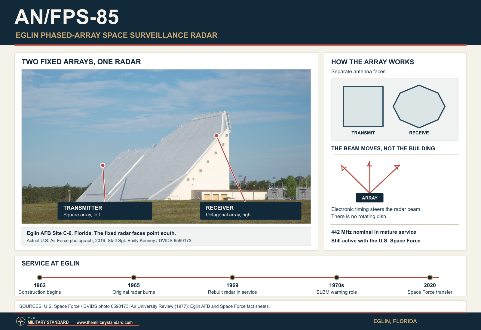
That one-site continuity can create a false impression that AN/FPS-85 had one fixed configuration. It did not. The nearly completed pre-fire system described in 1964 source material was not necessarily identical to the radar reconstructed after January 1965. The rebuilt system received design improvements before operational acceptance. Later modifications added missile-warning software, deep-space capability, new computers and processors, upgraded beam-steering controls, redesigned transmitter electronics, and eventually an all-solid-state replacement path for the original high-power tube transmitter modules. Specifications in different eras must therefore be tied to their source and date rather than flattened into a single timeless data sheet.
Strategic Need and the Choice of Eglin
The AN/FPS-85 grew out of the early space-surveillance crisis of the late 1950s and early 1960s. Sputnik and the rapid growth of Soviet missile and satellite programs created a requirement that went beyond seeing aircraft or even detecting an occasional ballistic missile. The United States needed to know what objects were in orbit, where they were going, whether a newly detected object matched an existing catalog entry, and how unfamiliar spacecraft behaved. Mechanical trackers and optical cameras could provide accurate observations, but the volume of orbital traffic and the need for rapid search and acquisition demanded a sensor that could look across a large volume of sky without waiting for a heavy antenna to turn.
Phased-array radar offered a fundamentally different solution. By controlling the relative phase of energy radiated from many antenna elements, the system could form a beam and steer it electronically. The antenna face itself remained fixed. The radar could shift the beam rapidly from one direction to another, revisit objects on different trajectories, and interleave search and tracking tasks far faster than a conventional pedestal-mounted dish. This architecture was technically difficult in the early 1960s because it required thousands of radio-frequency channels, accurate phase control, powerful computing, extensive calibration, and a building large enough to support the arrays and associated equipment. AN/FPS-85 was a national-scale attempt to turn that concept into an operational space-surveillance weapon system.
Eglin's geography was part of the design logic. Site C-6 lies east of the main Eglin complex in the Florida Panhandle, giving the radar a southern field of regard over the Gulf of Mexico, Caribbean approaches, and equatorial orbital paths. The array faces were mounted on the south side of the radar building at an approximately forty-five-degree inclination, allowing electronically steered coverage across a wide southern sector. That geometry was well suited to observing objects in many inclinations as they crossed the radar's field and later gave the site strategic value for submarine-launched ballistic-missile warning from southern ocean areas.
The site also benefited from Eglin's enormous controlled military reservation. A radar transmitting tens of megawatts of peak radio-frequency power required electromagnetic-control considerations, security, dependable utilities, and enough protected land to keep surrounding development from pressing immediately against the facility. The installation could draw on Eglin for roads, logistics, communications, emergency response, and base support while remaining physically separated from the main flying and weapons-test areas. This combination of southern viewing geometry, federal land control, and established Air Force infrastructure made Site C-6 a practical location for a radar that would have been difficult to place near a dense city.
Development Responsibility and Bendix
Air Force historical material assigns engineering responsibility for development of the space-tracking radar to Rome Air Development Center, with Bendix Corporation receiving the developmental contract. Contemporary electronics reporting identifies Bendix Radio Systems Division as the prime contractor for both the original and rebuilt AN/FPS-85. The contractor relationship is important because later corporate names can obscure the original role. AlliedSignal and Honeywell appear in later support-lineage descriptions because of corporate succession, while L3Harris appears in modern sustainment material. Those later names should not replace Bendix when describing the 1960s design and construction program.
Construction at Site C-6 began in October 1962. The project belonged to the generation of defense programs that tried to turn experimental phased-array technology into a continuously operating military sensor. The challenge was not simply to build a large antenna. Thousands of transmitter and receiver channels had to be manufactured, installed, calibrated, and controlled as one coherent aperture. Computer equipment had to schedule search and track functions, predict where targets should appear, steer beams, process returns, and pass observations into the national space-surveillance system. The power and cooling plants had to support a radar whose building was itself a major engineered structure.
Contemporary Electronics reporting in February 1964 described the nearly completed system as an automatic UHF radar intended for SPADATS service and capable of search and tracking at the same time. A second Electronics article in June 1964 described missile detection and tracking as the publicized A-1 priority and called the system, in effect, a southern ballistic-missile warning radar, while still identifying unknown-satellite detection and cataloging as the next priority. That public mission-priority description does not erase ADC's internal record that space detection was the mission the command later sought to protect from competing SLBM tasking. It does prove that missile use was embedded in the radar concept well before operational acceptance. Period descriptions also emphasized computer control. An IBM 7044 at Eglin exchanged digital tasking with SPADATS and fed a Bendix special-purpose radar programmer, so electronic beam steering depended on tightly coupled target predictions, search schedules, beam commands, measured returns, and track calculations.
The Original Frequency Record and a Major Source Conflict
One of the most important source-control issues in the AN/FPS-85 record is frequency. Mature operational and modern sources consistently place the rebuilt radar in UHF near 442 MHz. A late-1990s National Security Space Road Map gives an operating range of 437 to 447 MHz. Modern technical literature describes 442 MHz nominal operation with a 10 MHz bandwidth. Aethercomm's transmitter-modernization paper likewise identifies 0.437 to 0.447 GHz. These mutually reinforcing sources provide a strong technical baseline for the long-serving operational radar.
A 1965 federal handbook, however, reports something radically different. MIL-HDBK-162A, based on an unclassified Air Force Systems Command Form 81 dated 1964-08-31, lists AN/FPS-85 transmitter and receiver frequency as 120 to 150 MHz in one band. The handbook also gives 4160-volt and 120/208-volt, 60-cycle, three-phase electrical requirements. That entry is especially difficult because contemporary February 1964 Electronics reporting, also before the fire, explicitly placed the nearly completed radar in the 400 to 500 MHz band. The two pre-fire sources therefore conflict with each other before reconstruction is even considered. No located primary document yet explains whether the 120 to 150 MHz entry was a documentation error, a subsystem or planning value, or a short-lived configuration that had already changed by the time trade reporters visited the site.
The correct treatment is to preserve the conflict. It would be unsafe to erase the 1965 federal handbook because later sources are more familiar, and equally unsafe to apply 120 to 150 MHz to the operational radar documented for decades at roughly 442 MHz. The mature operational baseline is UHF 442 MHz nominal and 437 to 447 MHz, while the 120 to 150 MHz handbook entry remains an unresolved pre-fire source conflict. This is precisely the kind of problem that can arise when one designation spans a destroyed prototype-like installation, a rebuilt operational system, and sixty years of modernization.
The 1965 Fire
The first AN/FPS-85 never reached its scheduled Air Force takeover. On 1965-01-05, a major electrical fire destroyed the nearly completed radar complex. Contemporary Electronics reporting described the loss as a $30-million installation and said the fire destroyed a thirteen-story, block-square complex whose formal takeover had been scheduled for April 15. More than 25,000 radar elements, including transmitters, receivers, and antenna elements, were affected. Some ground-floor air-conditioning equipment survived, but the radar system itself was essentially lost.
Later Eglin and unit histories attribute the fire to arcing electrical equipment. The event was more than a construction accident. AN/FPS-85 was expected to close an important southern gap in the American space-detection and missile-surveillance picture, and its destruction forced the Air Force and Bendix to decide whether to reconstruct the original design or use the loss as an opportunity to improve it. The schedule impact was measured in years, not months. A system expected to enter testing in 1965 did not become an operational ADC sensor until late 1968 or early 1969, depending on which acceptance milestone is used.
The fire also influenced the architecture of the second radar. A 1966 Electronics report stated that Bendix remained prime contractor and that the rebuilt version would handle more targets, provide better resolution, and include greater protection against fire. The article also noted improved Doppler measurement intended to help distinguish closely spaced targets. That evidence establishes that the post-fire AN/FPS-85 was not simply a bolt-for-bolt recreation of the first installation. The reconstruction incorporated operational lessons and design changes before the radar ever entered routine military service.
Reconstruction and Operational Acceptance
Rebuilding the radar took several years because the program had to replace an enormous amount of specialized equipment while also revising design features. By 1968 trade-press reporting again described the AN/FPS-85 as a thirteen-story, air-conditioned radar building with separate transmitting and receiving arrays. The transmitter face was organized around a large matrix of replaceable modules, and the system used computer-controlled beam steering rather than mechanical rotation. The massive rebuilding effort turned the accident into a second development phase.
The Air Force took ownership of Site C-6 in September 1968, according to Eglin and unit histories. Aerospace Defense Command's SPACETRACK table gives December 1968 for Eglin C-6 and identifies the 20th Surveillance Squadron as the operating organization. Other Air Force histories use January 1969 or February 1969 for operational service, while Eglin celebrated fifty years of radar operations in April 2019. These dates reflect distinct turnover, assignment, technical, and operational milestones rather than evidence that one source must be discarded. Sturdevant specifically dates the beginning of SPACETRACK operations to January 29, 1969. That attributed day-level date supplements the broader service milestones; it does not establish that every acceptance and mission transition occurred on that day.
The most defensible chronology separates them. September 1968 marks Air Force ownership. December 1968 is the ADC program-table milestone and coincides with late-December transfer into Aerospace Defense Command's operational structure. January 1969 is widely used as the system's operational date in later technical references. February 1969 appears in Eglin historical summaries for commencement of space operations. The radar's history therefore records a late-1968 to early-1969 transition into full mission use rather than forcing several valid milestones into one artificial date.
Phased-Array Architecture
AN/FPS-85 uses separate transmitting and receiving arrays mounted side by side on the sloping south face of the radar building. The transmitter and receiver have physically separate but colocated apertures; this is not the geographically separated transmitter/receiver arrangement of the former NAVSPASUR fence. The transmitting aperture contains thousands of individual radiating elements and thousands of independent transmitter modules. The receiving aperture is larger and uses many more antenna elements feeding thousands of receiver modules. The fixed geometry eliminates a rotating antenna and allows the radar to create and redirect beams through electronic phase control.
Late-1990s National Security Space Road Map data describe 5,928 transmitter antennas arranged in a 78 by 76 pattern and 5,184 transmitter modules arranged in a 72 by 72 matrix. Modern technical sources often simplify the description to a 72 by 72 transmitting array of 5,184 powered elements. These statements are not necessarily contradictory. One count can refer to physical antenna elements while the other refers to powered transmitter channels. The receive side is documented as approximately 19,500 antenna elements associated with 4,660 active receiver modules. Older shorthand that says the radar had 5,134 transmitters appears in Air Force historical narratives, but the mature engineering literature strongly supports 5,184 active transmitter modules. For the original pre-fire complex, February 1964 Electronics reported a transmitter structure about 132 feet wide by 95 feet high and deep and a circular receiver structure about 195 by 145 by 145 feet. Those dimensions are preserved as pre-fire construction data rather than assumed to describe every rebuilt or later configuration.
The distinction between antennas and modules matters. The cited descriptions report physical antenna counts separately from powered transmitter and receiver channels. They do not establish the connection or purpose of every additional element. The late-1990s account reports 5,928 transmitter antennas and 5,184 transmitter modules when using the late-1990s configuration, while noting that many secondary descriptions compress the system to 5,184 transmitting elements. On receive, 19,500 crossed-dipole antennas are associated with 4,660 active receiver modules, again demonstrating that element count and module count are not interchangeable.
Beam Steering and Coverage
The array faces are inclined approximately forty-five degrees and point generally south. Electronic steering lets the radar move its beam across a broad sector without physical rotation. Public technical descriptions commonly give about 120 degrees of azimuthal coverage and an elevation field extending from a few degrees above the horizon to beyond zenith. An Air Force handbook lists roughly 3 to 105 degrees elevation, while Aethercomm describes steering from the horizon to approximately 15 degrees past zenith. These values describe a field of regard, not an aircraft-style altitude ceiling.
The fixed array has no rotation rate. This simple fact distinguishes AN/FPS-85 from most earlier ADC radars. Search coverage is produced by scheduled electronic beam positions rather than by an antenna making revolutions per minute. A mechanically rotating surveillance radar gets repeated looks because the dish comes back around. AN/FPS-85 gets repeated looks because its control system tells the array where to point next. The radar can therefore allocate time differently to search, confirmation, tracking, calibration, and special tasks as mission priorities change.
Technical literature gives a transmitting beamwidth of about 1.4 degrees at boresight and a narrower effective receive beam near 0.8 degree in some descriptions. Beam shape changes as the beam is steered away from boresight because projected aperture and phase errors change. For that reason a single beamwidth number is best treated as a reference condition, not a universal value across the entire 120-degree sector. The ability to form different beams electronically was more important operationally than any one static beamwidth figure.
Transmitter Power
The rebuilt AN/FPS-85 reached approximately 32 megawatts combined peak radiated power, but that system figure cannot be obtained by multiplying every transmitter's maximum rating. The authors of a 1994 Southwest Research Institute study described 5,184 modules in a 72 by 72 matrix, each rated for at most 10 kilowatts peak. They reported mean operating output of approximately 6 kilowatts per module at the time, which is broadly consistent with the stated array power. The 51.84-megawatt product of 5,184 and 10 kilowatts is only a nameplate sum, not an observed system operating level.
The same 1994 paper explains why the array did not act like thousands of identical ideal sources. Original tube transmitters were set near 8 kilowatts after maintenance, then gradually lost output, with individual units in service ranging from about 2.5 to 10 kilowatts. Their amplitude varied across the aperture, while phase alignment still required manual adjustment. Unequal amplitude and phase can reduce gain, move a beam, or raise sidelobes. The paper describes these as engineering problems motivating a redesign; it does not give a measured before-and-after performance improvement for a fully retrofitted radar.
Approximately 30 to 32 megawatts remains the source-supported historical combined peak range. Modern Aethercomm material gives about 6.2 kilowatts as a nominal legacy module value and describes replacement units configurable for outputs up to roughly 10 kilowatts. Neither the higher modern module capability nor a prototype result establishes a new accepted peak rating for the entire radar. Array rating, individual maximum, maintenance setting, and actual output are different quantities, and the available sources do not report a single value that applies to every configuration from 1969 onward.
Average RF Power and Duty Cycle
Average radio-frequency power is less securely defined than peak output. A 2021 review of space-debris radars prints 30 megawatts peak and 10 kilowatts average for AN/FPS-85, without explaining its averaging interval or operating mode. The original tube transmitter described by Southwest Research Institute in 1994 was rated for a duty cycle up to 0.5 percent. That is a limit for the dated module configuration, not evidence that the entire array constantly operated at that duty fraction. Search, track, calibration, and signature tasks use different pulse sequences and schedules.
Multiplying a 32-megawatt combined peak by 0.005 yields 160 kilowatts, but this is only a CALCULATED hypothetical full-array average at continuous use of the stated legacy duty fraction. It does not supersede the review's published 10-kilowatt figure, whose averaging convention remains unclear. Conversely, the 10-kilowatt number cannot be taken as a measured ceiling for every task. Skolnik's historical discussion explicitly says the radar computer had to schedule its functions so transmitter average-power limits were not exceeded, confirming that power management was an operating constraint rather than one static specification.
The 1994 T-1028A redesign targeted 520-microsecond pulses and 1.1-percent duty, approximately double the earlier 250-microsecond and 0.5-percent module limits. The authors reported successful tests of the prototype duty-cycle goal and sustained 9-kilowatt peak output at pulse widths exceeding 520 microseconds. These are prototype-unit test results. Because the same paper says complete array testing required replacement of all transmitter modules and that three-prototype long-term site operation was still pending, the enhanced duty cycle cannot be assigned to the operational radar as a whole.
Pulse Widths and Waveforms
AN/FPS-85 used a repertoire of waveforms rather than a universal pulse width or pulse repetition frequency. In the 1980 second edition of Introduction to Radar Systems, Merrill Skolnik's Table 8.1 lists seven historical operational waveform families and an eighth used to align transmitter and receiver modules. Long-range search and tracking used 250-microsecond frequency-modulated pulses; shorter 10-microsecond search and 1-microsecond track pulses served closer targets, with the latter also listed for short-range SLBM search. Those mode labels describe a dated configuration, not a certified current waveform inventory.
The same table documents three coherent forty-pulse burst modes. A 125-microsecond-pulse, one-second burst supported extended-range tracking and signature work; a 25-microsecond-pulse, 0.2-second burst served intermediate Doppler and signature tasks; and stepped-frequency 5-microsecond pulses in a 1.2-millisecond burst supported precision ranging. The eighth, 60-microsecond waveform was for module calibration. These details explain why a simple list of pulse lengths hides the radar's real operating method: beam direction, waveform, dwell length, and processing were selected together according to task.
Skolnik also describes computer arbitration when high-priority tracking conflicted with search. Following a possible detection, the system could rapidly revisit the same direction with a stronger or longer verification pulse rather than waiting for a rotating antenna to return. This was an operational advantage of electronic steering, but every such revisit consumed schedule and average-power capacity. The reviewed sources do not establish one PRF, one average RF output, or one waveform mix valid across the radar's whole service life; later missile, deep-space, and debris missions also changed software and processing.
Receiver and Signal Processing
The receiving array uses approximately 19,500 crossed-dipole antenna elements feeding 4,660 active receiver modules. The large receive aperture produces narrow angular resolution and supports formation of receive beams corresponding to the transmitter's electronically directed illumination. Calibration networks, local-oscillator distribution, beam-forming equipment, and receiver control are integral parts of the system. The receive architecture is therefore not a passive wall of antennas. It is an electronically organized measurement system whose many channels must remain phase coherent enough to form useful beams.
The 1965 fire created an opportunity to improve receiver technology. Secondary engineering histories describe the rebuilt system as moving toward lower-loss diode phase shifters and transistorized receiver components compared with the original design. The 1966 contemporary Electronics report independently confirms that the reconstruction was redesigned for better target capacity and resolution, although it does not provide a complete component inventory. The history therefore treats detailed component substitutions as source-qualified engineering evidence rather than as universally documented configuration facts.
Doppler performance mattered because the radar often had to distinguish nearby objects or separate a moving target from clutter and other returns. The post-fire rebuild was specifically reported as improving Doppler measurement. Later use for space-object identification and debris work exploited the radar's ability to collect not only positions but also radar signatures. By combining range, angle, Doppler, and repeated observations, the system contributed data for orbit determination, target discrimination, and radar cross-section characterization.
How the Radar Worked
In surveillance mode, computers generated a schedule of directions and waveforms that caused the transmitter array to form successive beams across the assigned sector. Each beam was created by setting the phase relationship among thousands of transmitter channels so their energy added constructively in the desired direction. Returns from objects in that illuminated volume reached the receiving array, where phase-controlled combining formed one or more receive beams. Signal processors detected candidate targets and compared measurements with predicted positions of cataloged objects.
When a return correlated with a known object, the radar could generate metric observations that refined the object's orbit. When a return did not correlate, the system could devote additional beams to confirmation and tracking. Rapid electronic steering was crucial because the radar could move from one target to another without waiting for an antenna to accelerate, slew, settle, and stabilize. The system could also interleave surveillance and tracking tasks, making it possible to support a large catalog while concentrating resources on high-interest objects.
For a tracked object, repeated measurements of range, azimuth, elevation, and Doppler produced a time history from which central space-surveillance processors could improve orbital parameters. Radar cross-section and signature data could support object identification or characterization. During missile-warning periods, software could instead allocate beams to low-elevation southern search volumes, rapidly establish ballistic tracks, and compute information useful for warning and attack assessment. The same fixed hardware thus supported different missions because beam scheduling, data processing, and communications changed how the aperture was used.
Range and Target Size
Public range statements vary because radar range depends strongly on target size, radar cross section, orbit geometry, integration time, waveform, and required measurement quality. An older Air Force fact sheet credited AN/FPS-85 with tracking a basketball-sized object at more than 22,000 nautical miles. That is more than 40,744 kilometers, not about 35,000 kilometers. The separately published 35,000-kilometer figure must therefore be treated as a different performance statement, not as a unit conversion. Air & Space Forces Association system descriptions continue to use a greater-than-35,000-kilometer basketball-size claim and say the radar can track or identify up to approximately 200 satellites simultaneously.
A current Eglin fact sheet uses a different comparison. It attributes to the Eglin radar the ability to find golf-ball-sized objects at approximately 7,000 kilometers, while the newer Space Fence is described as seeing basketball-sized objects at roughly 40,000 kilometers. These statements are not directly interchangeable because they use different target sizes and probably different performance definitions. The older geosynchronous basketball claim remains historically important, but current official wording should not be overwritten merely because earlier fact sheets used a more dramatic comparison.
The late-1990s National Security Space Road Map states that AN/FPS-85 could make roughly 10,000 observations per day and observe both near-Earth and deep-space objects simultaneously, with coverage exceeding 22,000 miles. This source is especially useful because it describes system workload rather than a single headline detection distance. A powerful space-surveillance radar earns its value by producing large numbers of accurate observations on many targets over time, not simply by achieving one extreme-range detection.
Deep-Space Capability
AN/FPS-85 was initially optimized for the southern space-surveillance mission, but it became a more explicit deep-space sensor through later upgrades. Air Force technical summaries give November 1988 as a major deep-space capability milestone. The improvement involved better use of pulse integration, processing, and range capacity rather than a new external antenna. The fixed arrays that had watched near-Earth objects for two decades could now contribute more effectively to the geosynchronous and high-altitude catalog.
This change was strategically significant because geosynchronous satellites had become central to communications, warning, intelligence, and military command and control. Deep-space surveillance required sensitivity to smaller returns at much greater slant ranges and accurate prediction of where a target would cross the radar's field. The radar's very high power-aperture product and programmable beam control made it useful even though Site C-6 could not see the entire sky at once.
Modern Mission Delta 2 material still calls the AN/FPS-85 the Eglin Phased Array Deep Space Radar. That current terminology confirms that deep-space tracking is not merely a historical modification preserved in old manuals. It remains part of the radar's identity within the Space Force space-domain-awareness enterprise, even as the 20th Space Surveillance Squadron also operates the much newer AN/FSY-3 Space Fence remotely from Eglin.
The Radar Building and Physical Plant
The radar building is inseparable from the weapon system. Later Air Force descriptions give an overall length of about 318 feet, a height of about 143 feet, approximately 250,000 square feet of floor space, and roughly 2.5 million cubic feet of enclosed volume. About 1,250 tons of structural steel and 1,400 cubic yards of concrete are cited in later system fact sheets. The arrays form the most visible part of the sloping southern facade, but most of the equipment needed to make them function is inside the structure.
Cooling requirements were substantial. Later system descriptions list three 500-ton chillers and two cooling towers. High-power transmitter modules, thousands of receivers, phase-control electronics, computers, power supplies, and people all added heat. Temperature stability also affects electronic phase and timing, so cooling was not simply a comfort system. The survival of some air-conditioning equipment during the 1965 fire was specifically noted in contemporary reporting because such plant represented a significant portion of the facility investment.
Electrical infrastructure included commercial prime power backed by uninterruptible supplies and emergency generators in later configurations. A widely reproduced Air Force fact sheet lists two 250-kVA uninterruptible power supplies and three emergency diesel generators rated at one 500-kW and two 400-kW units. These values are facility-support figures from a later configuration and should not be confused with the radar's radio-frequency output. The pre-fire federal handbook separately lists 4160 V and 120/208 V, 60 Hz, three-phase requirements, demonstrating that the radar depended on multiple distribution levels from its earliest design.
Fire protection became an especially important facility requirement after 1965. Contemporary June 1966 reporting described fire-wall compartmentation, automatic extinguishers and three quick-start 500-kW generators able to power water pumps independently of the radar supply. The report explained that loss of the shared electrical supply had prevented pumping water from nearby wells during the original fire. These rebuilt-system safeguards are distinct from generator ratings in later fact sheets. Later modernization also replaced aging tube and power-supply hardware that presented maintenance and reliability burdens. Because the system had only one operational site, a major facility failure could remove an important national sensor from the Space Surveillance Network. Redundancy in utilities, spares, trained personnel, and remote data paths therefore had strategic importance beyond normal base engineering.
Site C-6 Land and Environmental Context
A 2025 Air Force draft environmental assessment identifies Site C-6 as one of five Eglin cantonment areas and maps a bounded developed area within the larger reservation. An aerospace simulation paper separately lists a model point for the FPS-85 radar at 30.572394 degrees north, 86.214692 degrees west. That is a published approximate radar-facility point, not an Air Force survey, property centroid, or legal boundary. The January 2026 final assessment and finding of no significant impact describe programmatic future construction levels at C-6, including a preferred-alternative allowance of five acres of new disturbance. That figure is proposed disturbance, not the historic or present size of the installation.
Programmatic environmental review does not establish that every part of the radar site is uncontaminated, nor does a base-wide cleanup entry identify a radar-compound impact without a matching location. The Air Force assessment says individual projects still require site-specific environmental compliance review. It therefore improves the picture of current land management and potential physical change without supplying a defensible property boundary, exact C-6 acreage, or a completed compound-wide contamination history. The AN/FPS-85 remains an active sensor on an active military site, not a closed surplus radar property.
Computers and Control
AN/FPS-85 was computer-dependent from its conception. The pre-fire design was publicly associated with an IBM 7044 and Bendix radar-programming equipment. June 1966 reconstruction reporting specified three IBM System/360-series machines: two for online and backup system work and another for compiling and auxiliary tasks. A Philco 2000 at Colorado Springs supplied instructions to Eglin. Skolnik's later, dated description instead names two IBM System/360 Model 65 central processors, each with 131,072 32-bit words of core memory and a 14-microsecond basic add time. These are different reported configuration snapshots, not a reason to erase either record.
Skolnik states that historical radar programs occupied more than 1.25 million storage words, about 60 percent of them diagnostic decision tables used to locate faults. The radar computer also had to schedule search, track, waveform, and calibration activity while respecting transmitter power limits. That scale of diagnostic and scheduling work shows why the processor was part of the radar's sensing capability, not merely a display accessory. Later fact sheets describe IBM ES-9000 mainframes, interface cabinets, and Sun workstations, while the Air Force's space-surveillance history dates another radar-control computer replacement to 1994. None is a current equipment census.
Software repeatedly altered the value of the fixed aperture. A 1975 missile-warning change allowed the radar to track submarine-launched ballistic missiles; the 1988 deep-space improvement used processing and pulse integration; and a 1999 software package improved detection of smaller debris at human-spaceflight altitudes. A May 2000 higher-elevation software test enabled an intensive two-day debris campaign later reported to have produced more than 80,000 detections. These milestones concern the main radar-control and mission-processing environment. They must not be confused with the separate 486-class host computer proposed for T-1028A transmitter calibration in 1994.
SPACETRACK and SPADATS
In its initial operational role, AN/FPS-85 became part of the Air Force SPACETRACK network and the broader Space Detection and Tracking System, SPADATS. The national mission required sensors to discover new objects, correlate observations with the catalog, refine orbits, and report data to central processing and command centers. No single radar could see every orbit. The network combined phased arrays, mechanically steered radars, optical cameras, and other sensors at geographically diverse locations.
ADC's 1973 SPACETRACK table is valuable because it shows how the command categorized each sensor. Shemya, now Eareckson Air Station, had separate detection and tracking radars. Current Alaskan Command material lists Eareckson among the remote locations supported by the Pacific Air Forces Regional Support Center. Diyarbakir, later known as Pirinclik Air Station, similarly paired FPS-17 and FPS-79. Eglin C-6 is different: the FPS-85 is listed in the table as performing both tracking and detection. That distinction captures one of the reasons phased-array architecture mattered. AN/FPS-85 could search a volume of space, detect objects, and then redirect resources to tracking without relying on a separate fixed detection radar at the same site.
The radar's southern view filled a unique part of the network geometry. Spacecraft in low-inclination or equatorial orbits could be poorly served by sensors whose best coverage was farther north. Eglin's field of regard intersected many such trajectories. The system also contributed to catalog maintenance and radar cross-section observations. Later road-map material described Eglin as a source of near-Earth and deep-space observations and emphasized its ability to generate data at a workload equivalent to many mechanical trackers.
The 20th Surveillance Squadron and Operator Lineage
The 20th Surveillance Squadron became the primary operating unit as the Air Force took ownership in 1968. The organization's name changed repeatedly as the mission emphasis and higher command structure changed. Air Force historical summaries describe evolution from surveillance designations into the 20th Missile Warning Squadron during the SLBM-warning era, a return to the 20th Space Surveillance Squadron when space surveillance again became primary, and redesignation as the 20th Space Control Squadron in the early 2000s.
The unit's history reflects the radar's own mission changes. During the original space-surveillance era, crews concentrated on orbital detection, tracking, identification, and catalog support. During the late 1970s and early 1980s, missile warning became the primary mission while space surveillance continued. After PAVE PAWS coverage assumed the southern missile-warning burden, the unit returned to a space-surveillance focus. In the twenty-first century the mission broadened into space domain awareness and space control, with radar observations supporting characterization, intelligence, warning, and protection of space operations.
In September 2020, more than thirty officers and enlisted members of the 20th Space Control Squadron transferred from the Air Force into the newly created U.S. Space Force at Eglin. The organization later took the current title 20th Space Surveillance Squadron. Current Space Force material says the squadron has roughly 250 Guardians, civilians, and contractors and conducts continuous command-and-control operations for both AN/FPS-85 and the geographically separated Space Fence radar. The modern crew is therefore larger in organizational scope than the small console crew described in older AN/FPS-85 fact sheets.
Crew and Operations
An older Air Force system fact sheet described a representative AN/FPS-85 operating crew of three military personnel and three Department of Defense civilians: a crew commander, crew chief, space-console operator, radar maintenance technician, computer/communications-center operator, and motor-control-center operator. That six-person description should not be mistaken for the entire squadron or maintenance workforce. It represents a control-room or shift-team concept within a site supported by far more technicians, engineers, security personnel, administrators, contractors, and base-support organizations.
Continuous space surveillance requires round-the-clock operations. Objects do not stop crossing the field of regard outside normal duty hours, and an unexpected launch or breakup can require immediate attention. Operators therefore worked in shifts while maintenance personnel kept thousands of transmitter and receiver channels, computers, cooling systems, power equipment, and communications available. The modular architecture helped because a limited number of degraded channels did not automatically take the entire radar offline.
The operator's job was increasingly one of resource management rather than hand-steering an antenna. Computers generated schedules and predictions, but human crews supervised priorities, special tracking tasks, maintenance status, communications, and unusual events. The radar could be tasked against newly launched satellites, decaying objects, fragmentation clouds, high-interest foreign spacecraft, or missile trajectories. The value of a phased array lay in its ability to reallocate resources quickly when the mission changed.
Early SLBM Consideration Before Operational Service
AN/FPS-85's relationship to submarine-launched ballistic-missile warning began before the radar was operational. ADC Historical Study No. 34 records that in December 1962 NORAD commander General John K. Gerhart believed phased-array radars such as the FPS-85 then under construction at Eglin would probably be superior to frequency-diversity radars for SLBM detection if money were no object. Budget limits pushed the command toward cheaper modifications of existing FPS-24 and FPS-35 radars instead.
The issue remained alive in 1963. Air Defense Command's stated preference order for candidate SLBM sensors in April was FPS-49 first, FPS-85 second, followed by modified FPS-35 and FPS-24 systems. In May, ADC investigated whether emergency SLBM software could be added to the FPS-49 and FPS-85 without destroying their primary SPACETRACK missions. The study found that computer storage and mode-switching limitations could prevent simultaneous space and missile operation unless additional computing resources were provided.
ADC again proposed the FPS-85 in July 1964 as part of a minimum-cost interim SLBM system, with Eglin covering the Caribbean area while other radars covered eastern and western approaches. By November, however, the command had become concerned that using FPS-49 and FPS-85 for SLBM warning could interfere with their primary space-detection missions. The interim plan shifted toward modified SAGE long-range radars. This chronology is important because it proves that missile-warning potential was recognized from the beginning, but it also shows that FPS-85 was not originally built as a dedicated SLBM-warning radar.
The 1970s SLBM Mission
The strategic problem changed as Soviet missile submarines and longer-range SLBMs increased the threat from southern and offshore launch areas. The existing coastal warning network, including converted height finders, had limitations. AN/FPS-85 already looked south and had a phased array able to search and track without mechanical repositioning. The Air Force therefore returned to the concept that ADC had studied a decade earlier.
Air Force histories state that new software installed in 1975 gave the radar a practical SLBM-tracking mission. U.S. Naval Institute technical history says the radar was modified in 1973-1974 to provide warning of submarine-launched missile attack from the Caribbean and Gulf of Mexico direction. These statements fit together as a period of hardware, processing, and software work culminating in a mature operational mission by 1975. The evidence therefore supports treating 1973-1975 as an SLBM modernization period rather than selecting one date as the entire conversion.
Missile warning then became the unit's primary mission while space surveillance continued as a secondary mission. The radar's ability to form low-elevation southern search beams gave NORAD warning coverage that existing northern-facing strategic radars could not provide. Contemporary congressional discussion in 1976 still described the FPS-85's principal mission as satellite detection and tracking while noting its role augmenting the SLBM warning network, illustrating that mission labels differed depending on the organizational or policy perspective.
The PAVE PAWS phased-array warning radars were eventually built specifically for continuous SLBM warning and attack assessment. As southern PAVE PAWS coverage matured in the 1980s, AN/FPS-85 no longer needed to carry the same missile-warning burden. By 1987 the Eglin unit returned to space surveillance as its primary mission. This was not a retirement of FPS-85. It was a transfer of one mission to a purpose-built successor system while the older radar continued in the role for which it had originally been created.
Alternate Space Surveillance Center
From 1971 to 1984, the 20th Surveillance Squadron also hosted the Alternate Space Surveillance Center. Air Force histories describe the alternate center as providing computational support to the primary Space Surveillance Center at Cheyenne Mountain and being able, if necessary, to assume command and control of worldwide space-surveillance sensors. This gave Site C-6 a system-level role far beyond operating one radar.
The alternate-center function meant Eglin could contribute to continuity of national space surveillance if the primary center became unavailable or overloaded. It required communications paths, computing, procedures, trained operators, and access to network-wide data. The AN/FPS-85 building therefore supported not only local radar operations but also a backup command-and-control function connecting distributed sensors to the national cataloging enterprise.
This mission also illustrates why the site's large computer and communications infrastructure mattered. A radar observation becomes strategically useful only when it is correlated, processed, and disseminated. The alternate center placed part of that broader information-processing architecture at Site C-6. When the mission ended in 1984, the radar remained, but one layer of national command responsibility moved elsewhere as the Space Surveillance Network and its command centers evolved.
Operational Contributions to Space Surveillance
AN/FPS-85 has spent most of its life doing routine work that rarely becomes a headline. Thousands of daily observations refine orbits, identify objects, monitor maneuvers, support launch and reentry prediction, and maintain custody of satellites and debris. This continuous catalog work is the foundation of space domain awareness. Without repeated measurements, orbit predictions degrade and a large catalog becomes progressively less reliable.
The radar also supports special interest targets. Space-control units have described developing special reconnaissance fences or tailored search patterns to find and characterize newly launched or foreign satellites. The phased array is especially suited to these tasks because software can schedule unusual search volumes without mechanically modifying the antenna. The radar can allocate time to high-interest objects while continuing routine catalog support, subject to finite transmitter, receiver, and processing resources.
A 2008 Eglin report on a squadron award said the unit had developed special reconnaissance fences to track new foreign satellites and that AN/FPS-85 could observe a large portion of the manmade orbital population. Such operational evidence shows how a 1960s radar remained relevant in a much more crowded space environment. The hardware's enormous power and aperture gave later software and processing upgrades a strong physical foundation to exploit. Air Force historian Rick Sturdevant dates a replacement radar-control computer to 1994 and a new software package to 1999, enabling detection of smaller debris at human-spaceflight altitudes. These processing milestones are separate from the 1994 transmitter prototypes and May 2000 experiment. The Dahlgren relationship concerns a separate naval host and control-center mission, not another FPS-85 array. Naval Support Facility Dahlgren traces its installation origins to 1918 and took its current support-facility identity in 2005. Sturdevant dates the transfer ceremony for the NAVSPASUR fence and Alternate Space Control Center at Dahlgren to October 1, 2004; the fence then became the Air Force Space Surveillance System.
The May 2000 Debris Campaign
One of the clearest published examples of AN/FPS-85 being used as a scientific space-debris instrument occurred on 2000-05-11 and 2000-05-12. During ground testing of software that allowed higher-elevation operation, the radar was used in a two-day debris-measurement campaign. The peer-reviewed review reports more than 80,000 objects and 599 element sets from the experiment; these are the authors' reported products, not evidence that 80,000 distinct satellites entered the routine catalog.
That count should not be confused with 80,000 separately cataloged satellites. Debris experiments can count repeated detections and many small objects not maintained as routine catalog entries. The significance lies in the radar's sensitivity and ability to sample a debris population beyond the normal operational catalog. Such observations help researchers estimate the number and size distribution of orbital fragments, information essential for collision-risk models and spacecraft-protection planning.
The campaign also demonstrates the flexibility of an electronically steered array decades after construction. A software test changed the volume of space accessible to the radar, and operators exploited that temporary capability for a valuable measurement campaign. This is a recurring theme in AN/FPS-85 history: the massive fixed hardware stayed in place while new software and processors repeatedly extracted new mission value from it.
Radar Cross-Section and Space Object Identification
AN/FPS-85 has long contributed radar cross-section and space-object-identification information in addition to positional observations. Radar cross section is not simply physical size. It depends on shape, orientation, materials, wavelength, and aspect. A spacecraft can therefore produce a changing return as it rotates or changes orientation. Repeated measurements can help analysts distinguish one object from another or infer physical behavior.
Late-1990s space-surveillance planning material identified Eglin as an important source of RCS data. The radar's 442-MHz wavelength, high power, and ability to revisit targets give it a distinct measurement character relative to higher-frequency sensors. Combining Eglin observations with other radars and optical sensors improves confidence because different wavelengths and geometries reveal different aspects of a target.
Modern Space Force terminology places this work inside space domain characterization and recognition rather than simply catalog maintenance. Current Mission Delta 2 material describes the 20th Space Surveillance Squadron as executing tactical space-domain characterization and responsiveness. The vocabulary has changed, but the underlying logic is familiar: detect the object, maintain custody, determine what it is doing, and provide information useful to commanders and analysts.
1990s Transmitter Modernization
Keeping thousands of original tube transmitters operating had become a major sustainment problem by the early 1990s. The Southwest Research Institute authors reported an average of seventeen module failures per day at the time of their study, a dated maintenance burden rather than a modern failure rate. Each original T-1028 mixed the 85.3-MHz elevation and 14.7-MHz azimuth steering signals to a 100-MHz intermediate signal, then mixed with a 537-to-547-MHz master-oscillator input to make the 437-to-447-MHz output. A technician had to adjust phase at the module while another watched calibration equipment; the boresight procedure took several minutes after maintenance on a unit.
The redesigned T-1028A retained the original slide-in envelope and blind-mate connectors, limiting disruption to the transmitter face. It moved low-level mixing and intermediate amplification to solid-state electronics while retaining a single Eimac YU-176 triode in the final cavity amplifier. The intermediate amplifier delivered about 350 watts peak to a conservatively rated 9-kilowatt final stage. Low-power mixing reduced the required master-oscillator drive from approximately 100 watts to less than one watt at the redesigned module, potentially allowing the old tube-based master-oscillator amplifier cabinets to be eliminated if the array were converted. That cabinet removal was a projected system effect, not a documented completed installation.
An embedded controller added remote phase and amplitude adjustment, temperature and voltage monitoring, fault shutdown, and restart functions. Its serial commands traveled over the existing transmitter-output monitoring coaxial network on a separate RF carrier, avoiding a new control cable to each of 5,184 positions. A proposed centralized 486-class calibration host could scan the array and command amplitude taper and phase alignment, making beam shaping less dependent on manual two-person adjustments. Such control could reduce sidelobes or compensate for aging modules, but the paper does not report measured array-wide gain or sidelobe changes in operational service.
Prototype testing exceeded 12 kilowatts peak in one test and sustained approximately 9 kilowatts at pulse widths beyond 520 microseconds. The team also reported meeting the 1.1-percent duty goal and demonstrating the serial control link after a five-minute full-reflected-power test. Those results establish engineering feasibility for a redesigned module, not acceptance of a 12-kilowatt operational array. The authors explicitly said complete evaluation of automated tailoring required retrofitting every module; long-term operation of three prototypes at the Eglin radar was still a future test when they wrote. No reviewed primary record proves a complete T-1028A retrofit or gives its installation date.
A separate SPIE transmitter-design paper by the same authors is available here only as a publisher abstract. It confirms the contract's three-prototype aim and says an all-solid-state design appeared technically viable but too expensive for array-wide replacement at the time. The full companion phase-nulling paper supplies the component and test details above. This limited source strategy prevents the abstract-only paper from being treated as read in full or from supplying unverified circuitry, production, or deployment claims. The 1994 redesign also remains separate from the much later GaN replacement program described below.
Service Life Extension Program
By the 2000s, obsolete hardware and software created a broader sustainment problem. The Government Accountability Office reported in 2011 that an Eglin AN/FPS-85 Service Life Extension Program had been underway since 2006 because critical components were becoming obsolete and unsupportable. The program was part of a wider effort to keep aging Space Surveillance Network sensors viable when replacement systems were not yet available.
Air Force budget documents divided the modernization into phases including a Control and Signal Processor Upgrade and a Beam Steering Control Upgrade. These projects targeted the parts of the radar most vulnerable to electronic obsolescence. New processors could replace aging computers and interfaces, while new beam-steering electronics could preserve precise array control without relying on components whose original manufacturers and supply chains had disappeared decades earlier.
The SLEP illustrates why AN/FPS-85 survived. Its concrete structure, fixed apertures, location, and power-aperture product were still valuable. Replacing processors and control electronics was expensive, but far cheaper than immediately constructing an entirely new deep-space radar with equivalent southern coverage. The modernization strategy treated the radar as an enduring national sensor whose electronic core could be renewed around a physically durable aperture.
All-Solid-State Transmitter Replacement
Aethercomm documentation published in 2022 describes the next major transmitter transition. The company reported delivering solid-state transmitters in a program intended to replace every one of the 5,184 legacy tube transmitter modules. The new SSPA 0.437-0.447-10000 design uses modern gallium-nitride devices and radial power-combining techniques to reproduce or exceed the performance of the legacy final amplifier.
The modern module operates across the radar's 437 to 447 MHz band and can be configured for peak output up to about 10 kW. Aethercomm describes three-phase 480-VAC input for the new transmitter assembly and a power-supply architecture capable of supporting substantial average output at the module level. These are modern replacement-unit characteristics and should not be back-applied to the 1968 configuration.
The program is historically significant because it represents the planned completion of a technological cycle. The reviewed manufacturer account documents a replacement program and deliveries, not the completed installation of all 5,184 modules; no verified array-wide completion date is available. AN/FPS-85 entered service when vacuum tubes were the only practical way to generate the required UHF peak power in thousands of modules. Engineers in 1994 considered all-solid-state replacement technically feasible but uneconomical. By the 2020s, high-power GaN devices and modern combining techniques made that approach practical. The radar therefore survived long enough to undergo a transition that its original designers could scarcely have implemented economically.
Relationship to Space Fence
The current 20th Space Surveillance Squadron operates both AN/FPS-85 and the AN/FSY-3 Space Fence, even though the newer radar is physically located at Kwajalein Atoll in the Marshall Islands. U.S. Army Garrison Kwajalein Atoll provides installation support for joint mission partners; that Army host is distinct from the Space Fence equipment and its Space Force operators. Space Fence is remotely operated from an Integrated Radar Operations Center at Eglin. This arrangement makes Site C-6 a command-and-control node for two generations of phased-array space surveillance separated by roughly half a century.
The systems are complementary rather than a simple predecessor-successor pair. Space Fence is a modern S-band radar optimized for detection and tracking of much smaller objects, especially in lower orbital regimes, and its sensitivity greatly expands the number of detectable debris objects. AN/FPS-85 retains a distinct southern UHF aperture, high power, deep-space utility, and decades of mission integration. Current Space Force fact sheets continue to list the Eglin radar as active rather than describing Space Fence as its replacement.
Future Deep Space Advanced Radar Capability missions are also associated with Mission Delta 2 and the 20th Space Surveillance Squadron. DARC is designed to improve persistent deep-space surveillance through multiple geographically distributed sites. It may eventually change the workload assigned to FPS-85, but no current source establishes a one-for-one retirement date. The correct present status is therefore active, with newer sensors complementing and gradually redistributing missions around it.
Relationship to PAVE PAWS
PAVE PAWS is the clearest functional successor to the AN/FPS-85's former SLBM-warning role. The Eglin radar demonstrated that a fixed phased array could search a wide sector rapidly, form multiple task sequences electronically, and track ballistic missiles without a rotating antenna. During the 1970s and early 1980s it served as both an operational warning sensor and a practical proving ground for phased-array missile-warning concepts.
Purpose-built PAVE PAWS sites were designed from the beginning for continuous sea-launched ballistic-missile warning and attack characterization. They had different array architecture, frequency plans, processing, and geographic deployment. As those sites matured, the Air Force could return Eglin's radar resources to space surveillance. AN/FPS-85 therefore should not be described as an early PAVE PAWS model, but it belongs in the technological and operational lineage that demonstrated the value of electronically steered warning radars.
The relationship also shows how one radar can be replaced in one mission but remain active in another. PAVE PAWS did not make AN/FPS-85 obsolete as a space sensor. It removed the need for Eglin to spend a large share of its resources on missile warning. That distinction is important to understanding the system's succession. The radar itself was not replaced; its SLBM-warning function was transferred to newer systems.
Space Force Transition and Present Mission
The creation of the United States Space Force in December 2019 eventually moved the Eglin space-surveillance mission into the new service. On 2020-09-03, more than thirty members of the 20th Space Control Squadron transferred from the Air Force to the Space Force in a ceremony at Eglin. The radar continued operating throughout the organizational transition. Hardware that began as an Air Force Systems Command development program in the early 1960s became a Space Force weapon system almost sixty years later.
Current Space Force material identifies the unit as the 20th Space Surveillance Squadron under Mission Delta 2. It maintains and operates AN/FPS-85 and operates the geographically separated Space Fence. Mission Delta 2 describes the Eglin system as the AN/FPS-85 Phased Array Deep Space Radar and ties its output to tactical space domain awareness and U.S. Space Command warfighting requirements. This is a much broader operational vocabulary than the 1960s SPACETRACK mission, but it still depends on the same basic task of turning radar measurements into knowledge of objects in orbit.
The system remained active in 2026. Air & Space Forces Association's 2026 system reference lists one active AN/FPS-85 and describes the radar as capable of detecting, tracking, and identifying large numbers of satellites with approximately 120 degrees of azimuth coverage and roughly 32 MW combined output. The historical prime contractor remains Bendix, while modern sustainment is associated with successor and support organizations including L3Harris. No official retirement date is stated in the reviewed current sources.
Variants, Configurations, and Nomenclature
No formal AN/FPS-85A suffix has been identified in the controlling ADC sources. The equipment appears simply as FPS-85 in ADC's master list and SPACETRACK table. The most important configuration boundary is therefore not a letter suffix but the 1965 destruction and reconstruction. The original nearly completed system and the operational rebuilt radar shared the designation even though evidence shows that the second design incorporated significant changes.
The developmental term Electronically Steerable Array Radar, or ESAR, appears in later Air Force historical summaries and is useful as a project-era name, but it should not be treated as a separate JETDS equipment model. Similarly, modern marketing or sustainment identifiers such as Aethercomm SSPA model numbers describe replacement components rather than new radar designations. AN/FPS-85 remains the correct system-level designation.
The 120 to 150 MHz federal handbook entry remains an unresolved documentation conflict, not established evidence of a pre-fire versus post-fire frequency change. Until a modification order, system specification, or rebuilt-radar acceptance document establishes the transition, the history must stop short of asserting that the fire caused a deliberate move to 442 MHz. The documentary conflict is unresolved and does not establish a frequency transition caused by the fire.
Predecessor and Successor Relationships
AN/FPS-85 had no direct one-for-one predecessor at Site C-6. It emerged from a broader SPACETRACK system that relied on mechanically steered tracking radars, fixed missile-detection sensors, research radars, and Baker-Nunn optical cameras. Its real predecessor was therefore an operational concept: a network in which separate instruments searched, detected, tracked, and photographed objects with relatively slow mechanical or optical tasking.
The phased array consolidated more of that mission into one site by combining detection and tracking. ADC's table explicitly marks FPS-85 as both tracking and detection. That capability distinguished Eglin from SPACETRACK sites where a fixed detection radar had to cue a separate mechanical tracker. AN/FPS-85 did not eliminate other sensors, because network geometry still required multiple locations and phenomenologies, but it demonstrated how electronically steered arrays could perform many tasks on one aperture complex.
No single successor has replaced AN/FPS-85. PAVE PAWS replaced its principal SLBM-warning burden. Space Fence greatly improved near-Earth detection of small objects. Modern deep-space radars and planned DARC sensors expand high-orbit coverage. Yet the Eglin radar continues to operate because those systems add capability rather than exactly duplicate its location, frequency, power, and field of regard. Its succession history is therefore one of mission redistribution rather than a clean retirement-and-replacement event.
Preservation and Surviving Evidence
AN/FPS-85 is preserved by continued operation rather than museum display. The Site C-6 radar building, transmitter and receiver faces, control spaces, utilities, and decades of modified electronics remain part of an active military installation. No complete second museum set has been identified in the reviewed records; the operational system was not a fleet of transportable sets. The surviving artifact is the functioning site itself.
The active status limits physical access, but the documentary and photographic record is unusually strong. Eglin Air Force Base released public-domain photographs for the radar's 50th anniversary in 2019, including views of the dedication monument and unit leadership. Wikimedia Commons hosts a public-domain aerial view credited to the Air Force. Historical magazines show the original and rebuilt arrays, module architecture, fire damage, control consoles, and operations. Technical papers document transmitter redesign and modern solid-state replacement.
The 2019 anniversary ceremony also created a deliberate memorial layer at Site C-6. A monument honored five decades of operations and the personnel who kept the radar working. That commemoration is significant because the site remains operational while already being treated as historic. Few defense-electronics systems can mark a half-century of continuous service at their original location without having become purely ceremonial equipment.
Role in the Wider Military Network
AN/FPS-85 was never useful in isolation. During the ADC era it contributed observations to SPACETRACK and SPADATS, which combined data from radars and optical sensors to maintain knowledge of orbiting objects. During the missile-warning era it passed information into NORAD warning and attack-assessment networks. As Alternate Space Surveillance Center host, Site C-6 could support command and control of the wider sensor enterprise. Under Air Force Space Command and now the Space Force, the radar became one component of a distributed Space Surveillance Network and space-domain-awareness architecture.
Its greatest network value has always been geometry plus power. A southern-facing UHF phased array in Florida sees orbital and ballistic paths that northern sensors view differently or not at all. Observations from Eglin can be fused with other radars, optical telescopes, missile-warning sensors, intelligence systems, and now commercial and allied data. The radar does not need to see every object continuously. It needs to make accurate observations at the right moments so the larger network can maintain custody and understand behavior.
The current organizational arrangement reinforces that network role. The same 20th Space Surveillance Squadron that operates AN/FPS-85 remotely operates Space Fence at Kwajalein, while Mission Delta 2 integrates multiple sensor types and battle-management units. The Eglin site therefore links a 1960s UHF phased array to a twenty-first-century S-band radar and a global command structure. Its long history is not an example of technology standing still. It is an example of a durable sensor repeatedly reinserted into newer networks.
Legacy
AN/FPS-85's technical legacy begins with scale. It was the first large operational phased-array radar specifically designed for space surveillance, and it demonstrated that thousands of individually controlled channels could act as one electronically steerable aperture. The system showed that a radar did not need a rotating or slewing antenna to search a wide sector, acquire a target, and maintain multiple track tasks. That principle became fundamental to later missile-warning, air-defense, and space-surveillance radars.
Its operational legacy is equally important. The radar entered service to catalog satellites, became a serious candidate for SLBM warning even before it was completed, later carried the southern missile-warning mission, hosted an alternate national space-surveillance center, returned to its original orbital mission, gained deep-space capability, supported debris research, and finally became a Space Force sensor. Few systems illustrate the overlap between Cold War missile defense and modern space domain awareness more clearly.
Its sustainment history may be the most remarkable part of the story. A radar destroyed before initial acceptance was rebuilt, then modernized through several generations of computers, beam-steering equipment, transmitter electronics, and software. Vacuum-tube transmitter modules that once represented the state of the art eventually became candidates for full GaN solid-state replacement. The arrays and building endured while the electronics around them changed. AN/FPS-85 survived because its fundamental physical asset, a huge high-power aperture in a valuable location, remained useful long after individual components became obsolete.
Chronology
- 1962-10 Construction of the AN/FPS-85 radar begins at Eglin Air Force Base Site C-6, Florida, with Bendix as the primary contractor.
- 1962-12 NORAD commander General John K. Gerhart identifies phased arrays such as the FPS-85 under construction at Eglin as potentially superior to frequency-diversity radars for SLBM detection if funding were unconstrained.
- 1963-03 Air Force Systems Division review continues to consider additional FPS-85 radars among possible SLBM-warning approaches.
- 1963-04 Air Defense Command ranks FPS-49 first and FPS-85 second among preferred SLBM sensor candidates.
- 1963-05 ADC investigates emergency SLBM programming for FPS-49 and FPS-85 while trying to protect the primary SPACETRACK mission; computer-storage limitations are identified.
- 1964-07-17 ADC again proposes FPS-85 at Eglin as part of an interim SLBM-warning concept covering the Caribbean area.
- 1964-08-31 Air Force Systems Command Form 81 later cited by MIL-HDBK-162A records AN/FPS-85 at 120 to 150 MHz, creating a major unresolved conflict with the mature 442-MHz operational radar.
- 1964-11 ADC steps away from relying on FPS-49 and FPS-85 for the interim SLBM system because of concern that the mission could interfere with primary space detection.
- 1965-01-05 An electrical fire destroys the nearly completed original AN/FPS-85 and its thirteen-story radar complex before scheduled Air Force takeover.
- 1965-01 Contemporary reporting describes more than 25,000 radar elements affected and a roughly $30-million system loss.
- 1966 Bendix reconstruction proceeds with a redesigned radar intended to handle more targets, improve resolution and Doppler measurement, and provide better fire protection.
- 1968-09 The Air Force takes ownership of the rebuilt Site C-6 system; the 20th Surveillance Squadron becomes the primary operating organization.
- 1968-12 ADC's SPACETRACK table records Eglin C-6, 20 SSq, FPS-85, with the radar performing tracking and detection.
- Late December 1968 Later histories place the radar under Aerospace Defense Command operational control.
- 1969-01 Many later technical references use January 1969 as the radar's operational date.
- 1969-01-29 Air Force historian Rick Sturdevant dates the beginning of AN/FPS-85 SPACETRACK operations to this day.
- 1969-02 Eglin historical summaries place the beginning of space operations in February 1969.
- 1971 Site C-6 begins service as the Alternate Space Surveillance Center in addition to its radar mission.
- 1972 Air Force histories describe a growing allocation of Site C-6 surveillance capacity toward SLBM search as the southern missile threat receives greater attention.
- 1973-1974 AN/FPS-85 is modified to improve the southern SLBM-warning mission, according to later technical histories.
- 1975 New software gives the radar a mature SLBM-tracking capability; missile warning becomes the unit's primary mission while space surveillance continues.
- 1976 Congressional discussion identifies FPS-85 as an important augmentation to the existing SLBM-warning network while still noting its principal satellite-tracking role.
- 1979 The operating organization is redesignated 20th Missile Warning Squadron during the period when missile warning dominates the mission.
- 1983 The Eglin space and missile-warning organization transfers into the evolving Air Force space-command structure.
- 1984 The Alternate Space Surveillance Center mission at Site C-6 ends after roughly thirteen years.
- 1987 Purpose-built PAVE PAWS coverage assumes the principal southern SLBM-warning burden, allowing the Eglin unit to return to space surveillance as its primary mission.
- 1987 The unit returns to the 20th Space Surveillance Squadron designation in Air Force historical summaries.
- 1988-11 Major processing improvements give AN/FPS-85 formal deep-space capability in later Air Force technical histories.
- 1994-05-13 SPIE publishes the full peak-power-tailoring and phase-nulling paper, reporting T-1028A prototype results and pending site testing.
- 1994-06-01 SPIE publishes the transmitter-design paper describing three proposed operational prototypes; this is not an array-wide installation date.
- 1994 T-1028A bench tests meet prototype power and duty-cycle goals; the authors leave long-term site testing of three modules and complete array-wide evaluation for future work.
- 1994 A new radar-control computer is installed, according to the Air Force space-surveillance history.
- Late 1990s National Security Space Road Map data describe 437 to 447 MHz operation, simultaneous near-Earth and deep-space observation, more than 22,000 miles of range, and roughly 10,000 observations per day.
- 1999 A new software package improves detection of small debris at human-spaceflight altitudes, according to the Air Force space-surveillance history.
- 2000-05-11 Higher-elevation software testing supports the first day of a two-day intensive debris-observation campaign.
- 2000-05-12 The debris campaign concludes after more than 80,000 detections are reported in later peer-reviewed literature.
- 2003-02 The unit is redesignated the 20th Space Control Squadron as the Air Force broadens its operational space-control mission.
- 2004-10-01 The NAVSPASUR fence and Alternate Space Control Center at Dahlgren transfer to Air Force Space Command at an official ceremony; the fence becomes the Air Force Space Surveillance System.
- 2006 A formal AN/FPS-85 Service Life Extension Program is underway to replace obsolete and unsupportable hardware and software.
- 2008 Eglin reports the squadron using special reconnaissance fences and AN/FPS-85 observations to improve understanding of foreign satellites.
- 2011 GAO identifies AN/FPS-85 as one of the Space Surveillance Network sensors receiving a continuing service-life extension because of obsolescence risk.
- 2012 Air Force program documents continue Control and Signal Processor Upgrade and Beam Steering Control Upgrade work under the SLEP.
- 2019-04-18 Site C-6 holds the AN/FPS-85 50th anniversary ceremony and unveils a dedication monument honoring five decades of operations.
- 2020-09-03 More than thirty members of the 20th Space Control Squadron transfer from the Air Force into the United States Space Force at Eglin.
- 2022 Aethercomm publicly documents delivery of all-solid-state transmitter modules under a program intended to replace the radar's 5,184 legacy tube transmitters.
- 2022-2024 The operating organization takes the current 20th Space Surveillance Squadron identity under the Space Force space-domain-awareness structure.
- 2024 Space Force fact sheets identify the squadron as maintaining and operating AN/FPS-85 while remotely operating AN/FSY-3 Space Fence from Eglin.
- 2026-01 The Air Force final cantonment environmental assessment and finding of no significant impact include Site C-6 among five Eglin development areas; proposed disturbance is not compound acreage.
- 2026 Mission Delta 2 and current Air & Space Forces system references continue to list one active AN/FPS-85 at Eglin Site C-6 with no announced retirement date.
Information sources (37)
- PDFHistorical Data of the Aerospace Defense Command, 1946-1973
SOURCE FOR: ADC's exact AN/FPS-85 description, Eglin C-6 deployment, 20th Surveillance Squadron association, December 1968 date, and tracking-and-detection role.
- PDFRichard F. McMullen, Radar Programs for Air Defense, 1946-1966, ADC Historical Study No. 34
SOURCE FOR: 1962-1964 FPS-85 SLBM planning, ADC preference ranking, computer-mode concerns, Eglin Caribbean coverage proposal, and decision to protect the primary space mission.
- WEBEglin Air Force Base, Space Control Radar Celebrates Golden Anniversary
SOURCE FOR: the 2019 50th-anniversary ceremony, five decades of operation, Site C-6 identity, unit leadership, and public-domain photographs.
- WEBEglin Air Force Base, 20th Space Surveillance Squadron
SOURCE FOR: current squadron size, continuous operations, AN/FPS-85 and Space Fence responsibilities, and current space-domain-awareness mission.
- WEBUnited States Space Force, Mission Delta 2 - Space Domain Awareness
SOURCE FOR: current Mission Delta 2 organization, Site C-6 role, AN/FPS-85 Phased Array Deep Space Radar designation, Space Fence remote operation, and future DARC mission.
- WEBEglin Air Force Base, Eglin Squadron Joins Space Force
SOURCE FOR: the 2020 transfer of 20th Space Control Squadron personnel into the Space Force and official summary of the unit's changing mission and designations.
- PDFMIL-HDBK-162A / TM 11-487C-1, Radar Sets
SOURCE FOR: the 1965 federal AN/FPS-85 entry giving 120-150 MHz and 4160 / 120-208 V, 60 Hz, three-phase power requirements based on a 1964 AFSC Form 81.
- PDFElectronics, February 14, 1964, phased-array Space Track development report
SOURCE FOR: RADC technical responsibility, Bendix prime-contract role, 400-500 MHz pre-fire frequency, IBM 7044 computing, search-while-track operation, and original transmitter/receiver structure dimensions.
- PDFElectronics, June 1, 1964, "Southern comfort"
SOURCE FOR: the publicized pre-fire missile-warning priority, simultaneous satellite search and tracking concept, remote SPADATS tasking, and planned transition from experimental to operational status.
- PDFElectronics, January 25, 1965, "Air Force's $30-million ash heap"
SOURCE FOR: the 1965-01-05 fire, destruction of the thirteen-story complex, Bendix prime-contractor role, scheduled takeover, and scale of the loss.
- PDFElectronics, June 27, 1966
SOURCE FOR: Bendix reconstruction, improved target capacity and resolution, Doppler improvements, and greater fire protection in the rebuilt radar.
- WEBU.S. Naval Institute Proceedings, "The U.S. Navy: Phased Array Radars," April 1979
SOURCE FOR: the Bendix AN/FPS-85 SPADATS architecture, 5,184 transmitting elements, 19,500 receive elements, January 1969 operational date, and 1973-1974 SLBM modification period.
- WEBNational Security Space Road Map, Eglin
SOURCE FOR: 437-447 MHz operation, simultaneous near-Earth and deep-space observations, 120-degree coverage, more than 22,000 miles range, antenna/module counts, and approximately 10,000 observations per day.
- WEBGrimes, Major, and Warnagiris, "T-1028A/FPS-85 Radar Transmitter Design," SPIE, 1994
SOURCE FOR: stated three-prototype contract aim and 1994 economic comparison of hybrid and all-solid-state designs. Publisher abstract only; full design paper not reviewed. Quantitative module and test details are corroborated by the separately reviewed full phase-nulling paper.
- WEBMontgomery D. Grimes, J. Mark Major and Thomas J. Warnagiris, Peak Power Tailoring and Phase Nulling of the AN/FPS-85 Radar, SPIE volume 2154, 1994, pages 241-246
SOURCE FOR: original T-1028 signal chain and manual calibration, dated maintenance burden, T-1028A hybrid prototype design, remotely controlled power/phase tailoring, module tests, and explicit absence of full-array verification at publication. Full six-page paper reviewed; figures inspected.
- WEBBianchi et al., "Crowded Space: A Review on Radar Measurements for Space Debris Monitoring and Tracking," Applied Sciences, 2021
SOURCE FOR: 442 MHz, 10 MHz bandwidth, 5,184 transmitter modules, 30 MW published peak, 10 kW published average, 1.4-degree beamwidth, pulse lengths, receive architecture, and the May 2000 debris campaign.
- PDFAethercomm, "SSPA 0.437-0.447-10000 Transmitter Replaces Tube Transmitters AN/FPS-85 Radar"
SOURCE FOR: modern 437-447 MHz solid-state transmitter replacement, 5,184-module program scope, 32-MW combined legacy baseline, 6.2-kW nominal legacy module output, and modern GaN replacement architecture.
- PDFGovernment Accountability Office, GAO-11-545, Space Acquisitions
SOURCE FOR: the AN/FPS-85 Service Life Extension Program being underway since 2006 because of obsolete and unsupportable hardware and software.
- WEBAir & Space Forces Association, AN/FPS-85 Eglin Phased Array Radar
SOURCE FOR: current system status, one active radar, 32-MW combined output, broad target-capacity claims, 120-degree azimuth coverage, contractor/support lineage, and present space-domain-awareness role.
- WEBAir & Space Forces Association, 2026 USAF & USSF Almanac: Space Systems
SOURCE FOR: 2026 confirmation that AN/FPS-85 remains an active Space Force space-domain-awareness sensor.
- PDFAir University Review, September-October 1973
SOURCE FOR: period Air Force photographs and descriptions of AN/FPS-85 transmitter modules, receiver modules, control displays, and electronic steering during operational service.
- WEBFederation of American Scientists, AN/FPS-85 Spacetrack Radar
SOURCE FOR: Rome Air Development Center engineering responsibility, Bendix developmental contract, ESAR developmental name, late-December 1968 ADC control, and early phased-array space-surveillance context.
- WEBU.S. Air Force AN/FPS-85 fact sheet, historical reproduction at Radomes
SOURCE FOR: Dated-configuration building dimensions, chillers, backup electrical equipment, computer and communication equipment, representative six-person crew and historical unit chronology. Undated reproduction is not a 2026 equipment census; its erroneous SAC deactivation sentence is not used.
- WEBEglin Air Force Base, Premier space surveillance squadron located at Eglin, 2011
SOURCE FOR: Round-the-clock radar mission, Eglin support relationship, rebuilt operations in early 1969 and dated observation workload. Historical workload is not presented as a current rate.
- WEBEglin Air Force Base, 20th Space Control Squadron wins first General Lance W. Lord Award, September 26, 2008
SOURCE FOR: Special reconnaissance fences for new foreign satellites, Site C-6 and Dahlgren detachment roles, and the dated space-object identification mission.
- PDFU.S. Air Force, PB 2014, PE 0305940F, Space Situation Awareness Operations
SOURCE FOR: Original budget exhibit, page 2, documents FY 2012 processor integration/testing and beam-steering work; these are budget-program milestones, not a claim that the entire SLEP finished in 2012. Archival reproduction of the original government exhibit.
- PDFCongressional Record, September 14, 1976, Extensions of Remarks, page 30357
SOURCE FOR: Contemporary discussion of FPS-85 augmenting southern SLBM warning while still described as principally a satellite-detection/tracking radar. This is a congressional discussion, not a unit operational directive.
- WEBDVIDS, Space Delta 2 monitors deep space, image 6590173
SOURCE FOR: Actual photograph used in the approved graphic, credited to Emily Kenney; taken April 18, 2019, posted April 8, 2021, VIRIN 190418-F-SD165-1003; DVIDS labels the image public domain.
- PDFAir University Review, November-December 1977, printed page 20
SOURCE FOR: Caption explicitly identifies the octagonal receiver surface and square transmitter area, corroborating the graphic's face labels.
- WEBRick W. Sturdevant, From Satellite Tracking to Space Situational Awareness: The USAF and Space Surveillance, 1957-2007, Air Power History, Winter 2008
SOURCE FOR: Printed pages 13 and 18 establish the attributed January 29, 1969 SPACETRACK start, 1994 radar-control computer, 1999 software and October 1, 2004 Dahlgren/fence transfer. Printed page 23 footnote 64 identifies the former Pirinclik FPS-79 station. Relevant passages reviewed from the full official PDF.
- WEBAlaskan Command, official command history and organization
SOURCE FOR: Current support listing for Eareckson Air Station on Shemya; distinguishes the host installation from historical FPS-17/FPS-80 equipment.
- WEBU.S. Army Garrison Kwajalein Atoll, Mission Statement
SOURCE FOR: Army installation-support role for joint mission partners, distinguished from Space Fence equipment and its Space Force operators.
- WEBNaval Support Facility Dahlgren, About
SOURCE FOR: 1918 naval installation origins and November 2005 support-facility identity; distinguishes the Navy host from the historical Air Force control-center tenant.
- PDFMerrill I. Skolnik, Introduction to Radar Systems, Second Edition, McGraw-Hill, 1980, printed pages 213, 324 and 328
SOURCE FOR: dated 1980 historical tube-module description, seven operational waveform families plus calibration waveform, scheduling and average-power constraints, and two IBM System/360 Model 65 processors. This is the second edition, not the 1962 edition cited by the 1994 paper.
- WEBEglin Air Force Base Cantonment Areas, Draft Environmental Assessment, September 2025, Figure 1.1-6
SOURCE FOR: Air Force mapping of the Site C-6 cantonment area as distinct from other Eglin cantonments; not a legal parcel survey or radar-compound acreage.
- WEBEglin AFB Cantonment Areas Final Environmental Assessment, Finding of No Significant Impact, January 2026
SOURCE FOR: programmatic proposed development and five-acre preferred-alternative disturbance allowance at Site C-6, with site-specific project review still required; the disturbance allowance is not installation acreage or a clean-site determination.
- PDFDavid A. Vallado and Jacob D. Griesbach, Simulating Space Surveillance Networks, AAS 11-580, 2011, Tables 1 and 2
SOURCE FOR: published model location 30.572394 N, 86.214692 W for the Eglin FPS-85 radar. The authors explicitly label sensor locations approximate; this is not a surveyed Air Force parcel center or legal site boundary.