
Frequency-Diversity Long-Range Search Radar AN/FPS-35 Air Defense Radar
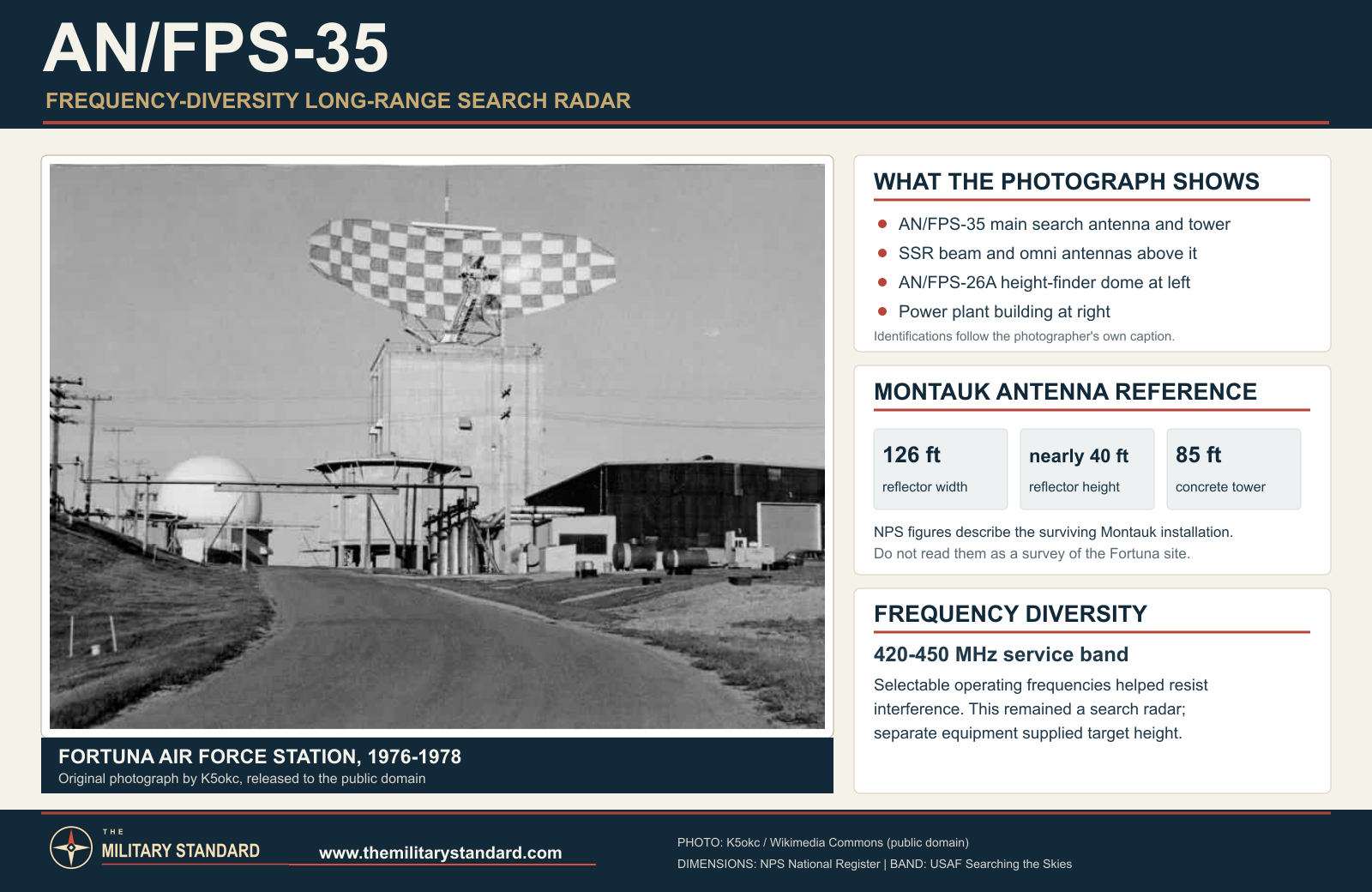
Common Name: Frequency-Diversity Long-Range Search Radar
System Family: RADC Frequency-Diversity Radar Program; Permanent Radar Network; SAGE; NORAD
Equipment Category: Fixed UHF frequency-diversity long-range surveillance/search radar
Frequency Band: UHF
Frequency MHz: 420-450 MHz in official USAF/Sperry-era service descriptions; MIT Lincoln Laboratory retrospective lists 400-450 MHz in its Air Force frequency-diversity radar table
Peak Power: Not established in reviewed model-specific primary technical documentation
Average Power: Not established in reviewed model-specific primary technical documentation
Service: United States Air Force, Air Defense Command / Aerospace Defense Command
Development lineage: Rome Air Development Center Frequency-Diversity Radar Program
Documented effective range: 200-250 miles for the preserved Montauk production installation in the National Register nomination
Altitude coverage: No authoritative universal numerical value established in the reviewed sources
Antenna: Elongated parabolic reflector, nearly 40 feet high by 126 feet wide at Montauk; approximately 70 tons rotating weight in Air Force historical sources
Antenna drive: Six 100-horsepower electric motors through reduction gearing at the preserved Montauk installation
Rotation rate: Reported 5 rpm
Primary role: Frequency-diversity long-range air surveillance and early warning for SAGE and NORAD
Initial operational fielding: December 1960, with the first production unit entering service at Montauk Air Force Station, New York; the development/prototype installation was at Thomasville Air Force Station, Alabama
Documented U.S. operational total: Twelve AN/FPS-35 radar installations ultimately became operational according to the Air Force historical study and specialist preservation record
Radar Manufacturer: Sperry Gyroscope Company, Division of Sperry Rand Corporation (Great Neck, New York)
Primary Role: Long-range air surveillance and early warning with frequency diversity and operator-managed ECCM; fielded as the search radar with separate height finders at normal SAGE sites
Detection Range: Montauk National Register nomination gives 200-250 miles effective range; do not substitute 1962 experimental SLBM-test or proposed modified-system range figures for baseline aircraft-surveillance coverage
Altitude Coverage: No authoritative universal numerical altitude-coverage value established in the reviewed model-specific sources
Antenna Type & Dimensions: Elongated parabolic reflector, nearly 40 ft high by 126 ft wide at Montauk; approximately 70-ton rotating assembly; perforated steel reflecting surface on welded space frame with feed boom
Antenna Rotation Rate: 5 rpm reported for the preserved Montauk production installation
Transmitter & Receiver: Frequency-agile UHF long-range search transmitter/receiver system associated with the AN/GLA-8 counter-countermeasure adjunct. MIT history documents frequency hopping and PRF jitter/stagger as family ECCM techniques. Exact production FPS-35 peak/average RF output and baseline pulse parameters remain unresolved pending a model-specific technical order.
Power Requirements: Total radar AC input not established. Montauk documentation records six 100-hp electric motors driving the antenna through reduction gears; this is antenna-drive capacity, not total FPS-35 electrical demand.
Introduced: Prototype/development installation at Thomasville AFS in the 1959-1960 period; first production unit entered service at Montauk AFS in December 1960; only four units operational by 1962; twelve U.S. operational installations ultimately documented
Retired: Retired site by site from the mid-1960s into the early 1980s; specialist site history identifies Montauk's 1981 shutdown as the last FPS-35 in the Air Force inventory
Replaced: Site-specific earlier search radars including AN/FPS-3, AN/FPS-20/20A, CPS-6B and related permanent-network equipment
Replaced By: No universal one-for-one successor. Paths included station closure, AN/FPS-67B-family replacement at Benton, FAA/shared surveillance radars, and later Joint Surveillance System coverage.
Associated Systems: AN/GLA-8; AN/FST-2; AN/FYQ-47 family common digitizers; AN/FSQ-7 SAGE; NORAD; BUIC; AN/FPS-6/6A/6B; AN/FPS-26/26A; AN/FPS-90; FAA joint use
Preserved Examples: Montauk AN/FPS-35 antenna and five-story concrete tower survive at Camp Hero State Park and were listed on the National Register of Historic Places on 2002-06-04. Other former sites retain towers or structural remnants. Hagley Museum and Library preserves a major 1960-1961 Sperry photographic collection; Peterson Air & Space Museum has displayed an FPS-35 model.
Equipment Identity
The AN/FPS-35 was built to solve a problem that became increasingly urgent as the Semi-Automatic Ground Environment network matured. The Air Force already possessed long-range search radars capable of finding aircraft far from defended cities, but Soviet electronic countermeasures threatened to make a predictable radar frequency a vulnerability. Rome Air Development Center responded with a family of frequency-diversity radars operating in widely separated parts of the spectrum. The AN/FPS-35 was the large UHF search member of that family. Sperry Gyroscope designed and built it as a fixed, high-capability surveillance radar whose operating frequency could be changed within a broad band, complicating the task of an enemy jammer trying to blind the continental warning network.Air Defense Command's own retrospective equipment list classifies the FPS-35 as "FD, Long Range Search." That concise phrase is unusually accurate. The system's defining characteristics were not simply size and range. It was a search radar, meaning that its normal duty was continuous broad-area surveillance in azimuth. It was long range, because it was intended to detect aircraft at distances appropriate to the outer warning layer of SAGE and NORAD. It was frequency diverse, because electronic-counter-countermeasures were designed into the concept rather than added as an afterthought. Unlike the AN/FPS-26, the FPS-35 was not a dedicated height finder. Sites normally paired it with AN/FPS-6, AN/FPS-26, AN/FPS-26A, or AN/FPS-90 equipment so that the full command system could obtain altitude as well as range and bearing.
The system was also physically unmistakable. At Montauk, New York, the surviving antenna is an elongated parabolic reflector nearly forty feet high and 126 feet wide. The National Register nomination describes the rotating assembly at about seventy tons and records six 100-horsepower electric motors driving the antenna through reduction gears at a reported five revolutions per minute. The five-story reinforced-concrete tower beneath it is about eighty-five feet high and roughly sixty feet square at the base. Those dimensions put the FPS-35 in a different physical category from ordinary tactical radars. It was a piece of strategic infrastructure, requiring a purpose-built building, a large mechanical bearing, heavy power and environmental support, specialized maintenance, and a permanent crew.
The combination of sophisticated electronics and very heavy rotating machinery became the radar's central historical tension. In electromagnetic terms, the FPS-35 was a forward-looking anti-jamming system. Mechanically, it demanded that an enormous antenna rotate around the clock with the reliability expected of a national warning network. The Air Force intended the large frequency-diversity radars to operate essentially continuously, with only a limited daily maintenance allowance. The bearing system did not initially meet that expectation. Frequent failures, long replacement outages, structural loading, wind exposure, and the practical difficulty of maintaining a seventy-ton rotating antenna became as important to the FPS-35 story as its frequency-agile electronics.
The radar therefore represents both the ambition and the limits of early SAGE-era engineering. It proved that a very large UHF frequency-diversity radar could be integrated into the continental air-defense network and could provide useful long-range surveillance for years. It also demonstrated that mechanical reliability could become the controlling factor in an electronic system. An antenna could have excellent RF performance and still fail the mission if its bearing could not keep it turning. The FPS-35 became a case study in how reliability, maintainability, electromagnetic compatibility, and civil engineering were inseparable from radar performance.
Development in the Rome Air Development Center Frequency-Diversity Program
The roots of the FPS-35 extend into the mid-1950s, when the Air Force was moving from first-generation permanent-network radars toward a more sophisticated electronic battlefield. Rome Air Development Center began a major frequency-diversity program intended to make continental surveillance harder to defeat with jamming. The strategy worked at two levels. Different radar types would occupy widely separated frequency bands so that a jammer optimized against one family would not automatically cover the others. Within an individual frequency-diversity radar, operators and electronics could shift operating frequency, forcing an adversary to follow or spread jamming energy over a wider part of the spectrum.A later MIT Lincoln Laboratory technical history places the AN/FPS-35 inside a five-radar prototype family. Its table lists the AN/FPS-24 as a 214-236 MHz surveillance radar, the AN/FPS-35 as a 400-450 MHz surveillance radar, the AN/FPS-28 as a 510-690 MHz surveillance radar, the AN/FPS-27 as a 2320-2680 MHz surveillance and stacked-beam height-information radar, and the AN/FPS-26 as a 5400-5900 MHz nodding-beam height finder. The exact service description for the FPS-35 is usually narrower, 420-450 MHz, but the Lincoln Laboratory table is important because it shows how the Air Force thought about the family as a whole. The radars were deliberately distributed across the spectrum.
The program was driven by the expectation that a sophisticated bomber attack would include electronic warfare. Chaff could create false or confusing returns. Spot jammers could pour energy into a known radar frequency. Noise jammers could raise the apparent noise floor. Repeater techniques could introduce deceptive signals. The Lincoln Laboratory history states that the common AN/GLA-8 signal-processing adjunct included a special anti-jamming console for a human counter-countermeasures operator. It specifically identifies frequency hopping and pulse-repetition-frequency jitter or stagger as techniques useful against active and passive countermeasures. The FPS-35 should therefore be understood as part of a man-machine defensive system in which operators selected and managed counter-countermeasure features rather than as an automatically invulnerable radar.
The technical lineage also runs through experimental UHF radars built before the FPS-35. Lincoln Laboratory's AN/FPS-31, also known in development as XD-1, began operation at Jug Handle Hill near West Bath, Maine, in October 1955. It was a huge UHF ground-control-intercept radar whose antenna and bearing problems provided direct experience with the difficult mechanics of rotating a very large reflector. The same technical history states that the measure of success achieved by the Jug Handle Hill radar, despite its bearing problems, paved the way for the lower-frequency Air Force frequency-diversity radars. The FPS-35 was not a simple production copy of FPS-31, but the earlier experimental work supplied both electromagnetic and mechanical lessons.
The Air Force did not immediately commit to a large production run. According to the Lincoln Laboratory history, Rome Air Development Center procured four AN/FPS-35 sets under a prototype contract for early installation at field sites and operation by Air Force crews. This approach deliberately put developmental equipment into realistic operational environments. A radar that performed well under contractor supervision at a test site still had to survive actual Air Force maintenance practices, weather, electromagnetic interference, around-the-clock schedules, and SAGE data requirements. The prototype-contract strategy exposed weaknesses before the whole network depended on the new design.
Thomasville Air Force Station, Alabama, became the principal prototype location identified in Air Force and preservation sources. Sperry photographs from the period include views taken there, and the station appears in ADC records with an FPS-35 in its later configuration. Thomasville's role matters because it separates development history from production history. The prototype installation tested and refined the system. Montauk Air Force Station, New York, is documented by the National Register nomination as receiving the first production unit in December 1960. Those are related milestones, but they are not the same event.
The test program overlapped with broader frequency-diversity evaluations in the Mobile, Alabama, Air Defense Sector. Lincoln Laboratory's retrospective notes that prototype forms of the selected systems were installed for test and evaluation at operational Air Force sites in Alabama, Louisiana, and Mississippi, with test programs beginning in 1959. This environment let the Air Force compare different frequency bands and operational methods within a real defense sector. It also meant the new radar family entered service through field experimentation rather than through a neat separation between laboratory development and later operational deployment.
The AN/FPS-35 reached the field at a moment when the Air Force was trying to modernize both sensors and command-and-control. SAGE Direction Centers depended on dependable radar data from many stations. The value of a new search radar therefore depended on more than raw detection range. It had to work with identification equipment, data-transmission systems, height finders, communications networks, and the schedules of interceptor-control units. This systems requirement helps explain why the FPS-35 took time to mature. A technically advanced search radar could not be judged in isolation from the larger SAGE architecture.
Frequency Range and the Source Difference
The most commonly cited Air Force service description gives the FPS-35 operating range as 420-450 MHz. David Winkler's official Air Force historical study uses that figure, and the Air Defense Radar Museum repeats it from the specialist equipment record. That band places the radar in UHF and is the best current figure for the service configuration represented on this page. It also fits the spectrum-management problems documented at Montauk, where a powerful UHF radar operating near civilian television services created local interference that required engineering attention.The MIT Lincoln Laboratory history gives 400-450 MHz in its table of Air Force frequency-diversity radars. That broader value should not simply be treated as an error. It may reflect program-level design coverage, prototype capability, a rounded family description, or the way the authors summarized the developmental requirement. Without a model-specific technical order that explicitly reconciles the two numbers, both belong in the historical record. The master technical field therefore uses 420-450 MHz as the operational Air Force description while preserving 400-450 MHz as the later technical-history value.
This difference illustrates a recurring problem in radar history. A developmental frequency range, a factory tuning capability, an authorized operating band, and frequencies actually used at a particular station are not automatically identical. The FPS-35 was designed around frequency diversity, so its relationship to the spectrum was more complicated than that of a fixed-frequency set. The correct historical method is to preserve the supported ranges and identify their source contexts rather than create false precision by choosing one number without explanation.
Range and Coverage
The National Register nomination for the surviving Montauk tower and antenna describes the FPS-35 as the largest frequency-diversity surveillance radar produced and gives an effective range between 200 and 250 miles. It also states that the new radar could extend Montauk's coverage as much as 250 miles eastward over the Atlantic. These figures are especially valuable because they are tied to the preserved production installation and were assembled from historical documentation during a formal federal historic-property evaluation.The figure should still be read as an effective historical coverage statement rather than as a universal guarantee against every aircraft. Radar detection range changes with target radar cross section, altitude, aspect, atmospheric propagation, clutter, antenna condition, receiver alignment, interference, and operator settings. A high-flying bomber may be detectable much farther than a small low-altitude aircraft hidden by the radar horizon. The master therefore records the 200-250 mile Montauk figure as documented effective range, not as a universal instrumented limit applying under all conditions.
This distinction is essential because the FPS-35 later participated in experimental ballistic-missile detection tests that produced much longer slant-range numbers. In 1962 modified FPS-35 sets at Manassas, Virginia, and Benton, Pennsylvania, attempted to detect launches from Cape Canaveral. NORAD and Air Force histories report detection performance on the order of hundreds of nautical miles in those tests, but those experiments involved modified configurations, very different targets, and a different mission problem. Those values do not belong in the baseline aircraft-surveillance range field.
The same safeguard applies to later proposals to modify the FPS-35 for missile warning. Air Force studies considered expensive changes that might have produced much greater detection ranges against missile-sized radar targets. The fact that engineers could calculate or propose such performance does not mean the standard production radar routinely provided it. The operational FPS-35 remained primarily an air-surveillance sensor, and its normal coverage must be described using aircraft-surveillance evidence rather than experimental missile-warning projections.
Antenna and Mechanical Architecture
The Montauk antenna provides the best surviving physical record of the production configuration. Its elongated parabolic reflector is nearly forty feet high and 126 feet wide. Thin perforated steel sheet forms the reflecting surface, with the holes reducing weight and wind resistance while remaining electrically reflective at the radar wavelength. A welded-steel space frame supports the curved surface, and a triangular tubular feed boom projects forward to place the receiving or feed element at the focus of the reflector. The geometry turned a massive steel structure into a directional UHF antenna capable of producing the narrow horizontal beam required for long-range bearing accuracy.The antenna's weight imposed extraordinary mechanical demands. Official Air Force historical summaries use a figure of about seventy tons. The National Register nomination discusses both the seventy-ton value and period Sperry promotional language claiming more than eighty tons, judging the lower figure more credible in light of the surviving structure. The page therefore uses approximately seventy tons as the historical operating figure while acknowledging that period manufacturer literature could describe a larger value. The difference is another example of why promotional figures and engineering records must be separated.
At Montauk, six 100-horsepower electric motors drove the antenna through reduction gearing. This is an antenna-drive figure, not the radar's total electrical requirement. The motors had to overcome inertia, bearing friction, wind loads, and the need to hold a stable rotational rate. A five-rpm search rate means one complete 360-degree sweep every twelve seconds. That cadence had to be maintained hour after hour while the antenna remained accurately leveled and the bearing carried enormous vertical and overturning loads.
The mounting pedestal transferred those loads into the tower through a massive central bearing system. Here the FPS-35 encountered its most persistent weakness. Large rolling-element bearings were technically feasible, but manufacturing tolerances, load distribution, lubrication, mounting accuracy, environmental exposure, and the practical difficulty of installing such a large component all affected service life. A bearing problem in a small machine might be a maintenance nuisance. A bearing problem underneath a seventy-ton radar antenna could stop a major sector sensor for weeks or months.
The Air Force's later bearing-improvement program makes the severity measurable. RADC Technical Report 71-81, summarized in later preservation literature, states that FPS-35 azimuth bearings failed on average about once every two years. Bearing changes could keep a radar shut down as long as three months and could cost as much as $175,000 for a single replacement operation. Those figures explain why the problem became a command-level logistics and engineering issue. Radar availability depended on an industrial supply chain for exceptionally large precision bearings, heavy lifting, alignment, structural access, and specialized technicians.
The program was not simply a search for stronger bearing material. The Air Force and contractors investigated load distribution, manufacturing quality, installation procedures, lubrication, different rolling-element arrangements, and alternate bearing concepts. The supporting documents to the Air Force radar history record multiple FPS-35 failures or near-failures and identify mount inaccuracies as a major concern. Higher-capacity roller bearings made from improved materials were among the corrective measures planned in the mid-1960s. The work fed a broader RADC expertise in very large antenna bearings that also affected the FPS-24 and later radar structures.
The mechanical problem had an important operational consequence. A frequency-diversity radar existed to make the warning network resilient against enemy action, but a failed bearing could remove the radar without an enemy transmitting a single watt of jamming. The Air Force therefore had to treat mechanical reliability as part of electronic counter-countermeasures in the broadest operational sense. A radar that could defeat jamming but could not rotate reliably did not provide resilient coverage.
Tower and Facility Design
The standard FPS-35 installation required a structure capable of carrying the antenna while also housing much of the radar's technical plant. At Montauk, the tower is a five-story reinforced-concrete building about eighty-five feet high and approximately sixty feet square. Ten-inch walls, integral concrete columns, waffle-slab floors, and four major interior support columns carried the antenna loads down through the building. The exterior checkerboard pattern of cast ribs made the tower visually distinctive even after the radar ceased operating.The tower was not an empty pedestal. The National Register documentation says it housed duty personnel and the heating, cooling, electronic generation, and signal-processing equipment required by the radar. This arrangement shortened RF and control paths between the antenna and major electronics while placing the operating equipment inside a controlled environment. The building therefore functioned simultaneously as antenna foundation, machinery enclosure, electronics plant, maintenance workspace, and operations facility.
Ten of the operational FPS-35 installations are generally described as using the massive concrete tower form, while Baker, Oregon, and Finley, North Dakota, used steel-frame tower arrangements. The exact structural details of every site were not fully verified in the reviewed primary drawings, so the page does not present one tower type as absolutely universal. The surviving Montauk structure is the best documented standard example. Baker is especially important because it introduced a radome and therefore required a separate surrounding support structure.
Baker Air Force Station's environment encouraged an unusual solution. Specialist Air Force radar history identifies Baker as the only FPS-35 installation successfully enclosed in a radome. The enclosure reduced direct weather loading on the antenna but added its own structural, maintenance, and RF-transmission problems. The fact that no general radome program followed shows how difficult it was to protect such a large rotating antenna economically. At other sites the reflector remained exposed, leaving the sail and bearing directly subject to wind, ice, temperature changes, and precipitation.
The size of the tower also changed the visual identity of the radar station. An FPS-35 site could be recognized from miles away by the enormous horizontal reflector and fortress-like building. At Montauk the tower became a maritime landmark. At Manassas the concrete structure remained a prominent feature long after the Air Force mission ended. At Fortuna the tower survived even after the antenna was destroyed and the station was largely demolished. The infrastructure outlasted the electronic equipment because reinforced concrete built to support tens of tons was much harder to remove than racks of obsolete electronics.
How the AN/FPS-35 Worked
In normal service the FPS-35 performed the same basic geometric task as other search radars. The antenna rotated continuously in azimuth. The transmitter emitted short pulses of UHF energy into the directional beam. When a pulse struck an aircraft, a small portion of the energy reflected back to the antenna. The time between transmission and reception gave range, while the antenna's angular position gave azimuth. Repeating the measurement across each rotation built a surveillance picture of aircraft moving within the radar's coverage.The difference lay in the way the system could manage frequency and countermeasures. A conventional fixed-frequency radar presents a jammer with a relatively simple problem: determine the radar frequency, generate enough energy at that frequency, and attempt to mask or confuse the receiver. A frequency-diversity radar can move among frequencies within its operating band. The jammer must then follow the radar's changes rapidly or spread its energy across a wider spectrum, reducing the amount of power concentrated on any one frequency. The Air Force frequency-diversity program also combined this with other counter-countermeasure techniques and operator controls.
The AN/GLA-8 adjunct was part of that operational concept. Lincoln Laboratory's technical history describes it as common equipment associated with the frequency-diversity radars and notes a special anti-jamming console for the human CCM operator. Frequency hopping, pulse-repetition-frequency jitter or stagger, and other measures could make coherent or repetitive hostile interference less effective. This required skilled operators who understood both the radar picture and the behavior of jamming. The system's flexibility was an advantage only if crews knew when and how to use it.
The FPS-35 remained a search radar rather than a complete three-coordinate system. Once it detected and tracked an aircraft, the SAGE network still needed altitude. Dedicated height finders at the same station could be cued to the target's range and bearing. A station might operate AN/FPS-6, AN/FPS-26A, or AN/FPS-90 height-finding equipment alongside the FPS-35. Data-processing systems then combined the sensor information for transmission to a SAGE Direction Center. The repeated pairing in ADC site tables confirms that this was the normal architecture.
This division of labor was efficient for the era. The huge search antenna continuously watched all azimuths, while the height finder concentrated on selected tracks requiring altitude information. SAGE computers could then create tracks, correlate identification information, and support interceptor control. The FPS-35 was therefore not an isolated radar display. It was the long-range horizontal surveillance component in a larger chain linking antenna, receiver, signal processing, identification, height measurement, digitization, communications, computers, controllers, and interceptors.
SAGE and NORAD Integration
The FPS-35 entered service after SAGE had already transformed continental air defense. SAGE replaced many manual plotting and voice-relay functions with digital data transmission and large centralized computers. Radar stations supplied track information to Direction Centers, where computers assisted operators in building the recognized air picture and directing interceptor aircraft or missile defenses. A new search radar had to fit that system without forcing the Air Force to rebuild the command network around it.Montauk's National Register history describes long-range radar data being transmitted to the regional Direction Center, which then coordinated height and range-finding activity and interceptor response. The station had already entered SAGE service before the FPS-35 arrived, so the new radar became a sensor upgrade inside an existing command architecture. This was typical of the deployment program. Most FPS-35 installations were established radar stations receiving a new search set, not new installations created solely for the radar.
The exact data-processing hardware varied by station and year. AN/FST-2 coordinate-data equipment was common in the classic SAGE period, and later sites converted to common digitizers such as the AN/FYQ-47 family. The FPS-35 therefore had a longer systems life than any one data processor. A radar installed during the early 1960s could continue operating while the electronics that formatted and transmitted its data changed around it.
NORAD provided the operational framework above the station and sector level. The radar's purpose was not merely to help a local controller see airplanes. It contributed to the continental warning picture of approaches to the United States and Canada. Stations at Montauk and Manassas guarded eastern approaches, while Antigo, Selfridge, Sault Ste. Marie, Finley, and Fortuna watched northern routes. Boron and Fallon contributed to western coverage. Baker added Pacific Northwest surveillance. The twelve installations were geographically distributed to strengthen high-priority sectors rather than forming a uniform nationwide grid.
The frequency-diversity concept also worked at network level. A hostile bomber approaching North America could encounter radar coverage in VHF, UHF, S-band, and other frequencies. The FPS-35 made the UHF portion of that mix less predictable. The value of the system therefore came partly from diversity across the whole radar network. Even if an adversary had excellent knowledge of one radar type, that knowledge did not automatically defeat the other frequency-diversity families or the many conventional radars still in service.
Early Fielding and Program Difficulties
The first production AN/FPS-35 entered service at Montauk Air Force Station in December 1960. The choice of Montauk was strategically and technically significant. The station sat at the eastern end of Long Island, facing the Atlantic approaches to the New York metropolitan region. It was already a long-established radar location and SAGE participant. Placing a new long-range frequency-diversity sensor there provided operational value while exposing the radar to a demanding coastal electromagnetic and weather environment.The program did not mature quickly. The official Air Force historical study states that problems hampered deployment and only four units were operational in 1962. That slow pace is consistent with the bearing record, field-reliability concerns, and the time required to integrate the new equipment at existing stations. Sperry itself presented a technical paper on field reliability of the AN/FPS-35 in 1963, evidence that reliability was not a minor afterthought but a recognized engineering problem during the initial deployment period.
Despite those difficulties, twelve installations ultimately became operational in the United States. The modest quantity reflects both the size and cost of the system and the fact that the Air Force never intended every radar station to receive one. The FPS-35 was one specialized element in a much larger sensor inventory. Many sites continued using modified FPS-20-family radars, FPS-7s, FPS-24s, or other systems. The frequency-diversity program added resilience and capability selectively rather than replacing the entire permanent network.
The radar's limited production also magnified maintenance problems. A bearing or antenna part was not a commodity component used by hundreds of systems. Specialized spares had to support a fleet of only about a dozen operational sets, each located at a strategically important station. When a major mechanical component failed, the Air Force sometimes resorted to transferring equipment from another site or adapting a spare developed for related experimental work. This fleet-management reality appears clearly in the histories of Fortuna and Manassas.
Montauk: First Production Unit and Radio-Frequency Interference Montauk became the most important FPS-35 site because it combined first-production status, serious early interference problems, long service, and unique preservation. The National Register nomination records the first production unit entering service there in December 1960. The radar's size and power extended surveillance far eastward over the Atlantic, but the same electromagnetic reach produced an immediate problem on the ground. Local residents complained that the radar interfered with television and radio reception.
The interference forced the Air Force to remove the radar from full-time service in 1961. Full operation resumed in 1962 after modifications intended to reduce the problem. This event is historically important because it demonstrates that spectrum compatibility was part of fielding a high-power frequency-diversity radar. The system could not simply use any frequency or operating mode it wanted without regard to nearby civilian services. Montauk lay in a densely populated communications environment, and the radar had to coexist with television, radio, military communications, and other electronic systems.
The broader RADC research program anticipated this kind of problem. Lincoln Laboratory specifically noted concern about colocating UHF ground-air communications with large VHF or UHF radars such as the FPS-24 and FPS-35. The experimental Boston Hill radar provided a facility for studying radio-frequency-interference problems. Montauk then supplied the operational lesson. A system that had been designed to resist enemy electronic interference could itself become a source of harmful interference if emission control, filtering, tuning, shielding, and site coordination were inadequate.
Specialist recollections from Montauk add a smaller example. Sperry engineers investigating a spurious radar signal traced it to shielding covers that had not been installed on nearby troposcatter communications exciters. Replacing the covers eliminated the interference. The recollection is not a substitute for a formal engineering report, but it illustrates how sensitive a high-gain radar receiver could be to local emitters. The electronic environment of a SAGE site contained many transmitters, and good electromagnetic compatibility depended on details as mundane as cabinet shielding.
Montauk's radar remained operational after the early problems were corrected. Dedicated height finders continued beside it, including FPS-6 and later FPS-26 equipment. The station also participated in FAA joint use for a period before civil coverage shifted elsewhere. The survival of the tower and antenna after the Air Force mission ended turned an operational liability into a preservation advantage. Because the huge structure was not demolished, it became the only essentially complete FPS-35 antenna-tower combination still standing.
Manassas and Benton: The 1962 Missile-Detection Experiment
The changing strategic threat briefly gave the FPS-35 a mission far beyond bomber surveillance. By the early 1960s the Air Force and NORAD were increasingly concerned about submarine-launched ballistic missiles. A radar that could detect the upward-moving missile or associated phenomena soon after launch might provide valuable warning to the National Military Command System. In December 1961 the Air Force asked Air Defense Command to evaluate whether the frequency-diversity radars could contribute.Modified AN/FPS-35 sets at Manassas Air Force Station, Virginia, and Benton Air Force Station, Pennsylvania, became the principal test radars in the summer of 1962. Air Force historical accounts state that the systems attempted to track Polaris, Minuteman, Titan, and Thor-Delta launches from Cape Canaveral. The concept was attractive because the large UHF antennas already existed and could potentially provide a new warning mission without waiting for an entirely new nationwide sensor network.
The tests did not justify operational adoption. The official Air Force historical study says the FPS-35 showed only marginal ability to detect missile launches. Prince William County's history of Manassas similarly states that the results were marginal and the FPS-35 was never adopted as a missile-detection system. NORAD historical material records performance far below the desired warning capability. The experiment therefore remained an instructive branch in the radar's history rather than a permanent mission change.
The failure was still useful. It demonstrated that long-range aircraft surveillance and ballistic-missile warning were not interchangeable problems. A radar optimized for continuous rotating air search had different geometry, processing, revisit time, antenna pattern, and target characteristics from a purpose-designed missile-warning radar. The tests helped define what would be required of later SLBM detection systems. The baseline FPS-35 remained an air-defense search radar, and the experimental missile ranges are intentionally kept out of its normal specification fields.
Manassas also demonstrates the complexity of deploying the radar. County historical documentation states that the massive FPS-35 replaced the site's FPS-3 and took almost a year to become fully operational because of its size and complexity. In 1963 the station added an FPS-26A height finder while retaining another height-finding channel. Manassas closed in June 1965, giving its expensive radar a relatively short local service life. Its antenna reportedly became valuable as a replacement asset elsewhere, showing how the small FPS-35 fleet was managed as a reusable national resource.
Benton remained in service much longer. Its FPS-35 became operational in 1962 after similar installation problems and later operated at a joint Air Force-FAA site. The station also used dedicated height finders and eventually newer digital processing. Around 1974 the FPS-35 was replaced by an FPS-67B-family search radar, while the location continued serving civil and military surveillance. Benton therefore illustrates a different retirement path from Manassas: the radar was not removed because the station closed but because a more supportable search sensor took over its role.
Fortuna: Wind Damage and Emergency Radar Recovery
Fortuna Air Force Station, North Dakota, produced the most dramatic FPS-35 mechanical incident. ADC records show the station operating the radar as its long-range search set with separate height-finding equipment. During the winter of 1964, a fierce windstorm destroyed or toppled the huge FPS-35 antenna. Unit-history and specialist accounts place the event in 1964, while some later secondary summaries give a 1966 date. The stronger unit-history sequence supports winter 1964, and the discrepancy is preserved rather than silently erased.The incident exposed the operational consequences of losing a unique search radar. Fortuna could not simply order another complete FPS-35 and install it immediately. Temporary search capability was established using an available FPS-66-family radar on a vacant tower while the station waited for a replacement antenna. An eyewitness account recalls the temporary system still being troublesome during a 1964 operational-readiness inspection. The emergency arrangement kept some coverage available but did not instantly restore the original radar's performance.
The replacement antenna is widely reported as having come from Manassas after that station closed. A separate MIT Lincoln Laboratory technical history adds another intriguing detail, stating that the Boston Hill experimental radar antenna was later demounted and used to replace an AN/FPS-35 antenna damaged by high winds at an operational Air Force site. These statements create an equipment-lineage question that should not be flattened without serial-number or transfer documentation. It is possible that more than one major component moved through the replacement process, or that later recollections compressed separate transfers.
The critical historical point is secure even if the exact donor-antenna chain remains unresolved. The Air Force treated large radar antennas as recoverable strategic equipment and moved major assemblies between sites when necessary. Fortuna's 1964 loss illustrates why spare bearings, sails, drive parts, and heavy structural components mattered to national readiness. A radar network built around a small number of expensive unique sets required logistics plans for failures that ordinary electronics maintenance could not solve.
Fortuna eventually returned its FPS-35 to service and continued operating until 1979. The station incorporated BUIC backup-control capability and remained part of the northern defense system long after the emergency. The FPS-35 tower survived after the radar station was largely demolished. That physical remnant preserves the scale of the installation even though the antenna itself is gone.
Baker and the Only Successful FPS-35 Radome
Baker Air Force Station, Oregon, faced another environmental problem: how to protect the large exposed antenna from severe weather. Specialist preservation records identify Baker as the only FPS-35 installation successfully enclosed within a radome. The solution required a structure large enough to surround the enormous rotating antenna without interfering with its movement or distorting the radar beam beyond acceptable limits.The Baker installation shows that radomes were not automatically beneficial. A large enclosure adds wind area, structural weight, cost, maintenance, and RF loss. The radome itself must survive storms while preserving a sufficiently uniform electromagnetic path for the radar. The experience of other large Air Force radar systems, especially the FPS-24 at Mount Hebo, demonstrated that enormous radomes could become failure points of their own. Baker's successful enclosure was therefore a site-specific engineering achievement rather than the beginning of a standard FPS-35 modification.
ADC records place FPS-35 and FPS-6 equipment at Baker in 1963, with later changes to the height-finding channel. The 821st Radar Squadron operated the station until inactivation in June 1968. The short Air Force life of the site contrasts with the engineering effort invested in its radome. Network consolidation could make an expensive specialized structure unnecessary only a few years after it was completed.
The Baker radar equipment and original tower no longer provide a complete preserved example. Specialist histories record later reuse of the radome structure, but the equipment-history page does not treat those reuse claims as equivalent to preservation of an operational FPS-35. The better-preserved system remains Montauk, where the actual antenna and tower survived together.
The Twelve Operational U.S. Sites
Air Force and specialist sources agree that twelve FPS-35 installations ultimately became operational in the United States. The commonly documented locations are Antigo Air Force Station, Wisconsin; Baker Air Force Station, Oregon; Benton Air Force Station, Pennsylvania; Boron Air Force Station, California; Fallon Air Force Station at or near Naval Air Station Fallon, Nevada; Finley Air Force Station, North Dakota; Fortuna Air Force Station, North Dakota; Manassas Air Force Station, Virginia; Montauk Air Force Station, New York; Sault Ste. Marie Air Force Station, Michigan; Selfridge Air Force Base, Michigan; and Thomasville Air Force Station, Alabama.The list needs one important qualification. Brunswick, Maine, appears in planning material as a proposed FPS-35 location but was not part of the operational twelve. Development programs generated many planned assignments that disappeared because of budgets, construction issues, changing coverage, equipment availability, or station closure.
ADC's retrospective tables confirm many of the operational locations directly. Antigo and Selfridge appear with FPS-35 equipment in the 1963-1972 Z-site tables. Montauk is shown with FPS-35 and dedicated height finders. Manassas and Boron appear with the radar in the permanent-network records. Baker and Fallon appear in the mobile-phase tables and later Z-site records. Thomasville's final configuration includes FPS-35 with two FPS-90 height finders. Fortuna appears with FPS-35 as a primary search set and later FPS-26A support.
The distribution was strategically uneven because the radar was not a generic replacement for every station. The Great Lakes and northern plains received several sets, strengthening likely bomber approaches. The East Coast received Montauk, Benton, and Manassas, protecting major population and command regions. Boron and Fallon gave the West a share of the frequency-diversity capability, while Baker covered part of the Pacific Northwest. Thomasville retained its developmental significance in the Southeast. The pattern combined test needs, strategic priority, and the practical availability of sites capable of supporting the huge structure.
Antigo and Selfridge
Antigo Air Force Station, Wisconsin, illustrates a comparatively straightforward operational installation. ADC records show the station in SAGE service with an FPS-35 search radar and multiple height-finding configurations. The station's equipment changed around the FPS-35 as older FPS-6-family equipment was adjusted and FPS-90 capability was added. This is the normal pattern for a large search radar embedded in a living site. The radar did not define every part of the installation, and other sensors continued to evolve while it remained the long-range search component.
Selfridge Air Force Base, Michigan, likewise carried an FPS-35 in the SAGE period. ADC records pair it with FPS-6A and later FPS-26A height-finding equipment. Selfridge was more than a remote radar hill. It was a major Air Force base with interceptor, command, and support functions, so the FPS-35 operated inside a complex electromagnetic and organizational environment. That setting made integration, interference control, and shared base support particularly important.
The two Michigan-Wisconsin region installations help explain why the radar's 420-450 MHz band mattered strategically. Northern approaches across Canada and the Great Lakes were central Cold War bomber routes. Long-range UHF surveillance added another frequency band to a region already covered by multiple radar types. The radar's value came from overlapping coverage and electronic diversity rather than from any one station operating alone.
Finley, Fortuna, and the Northern Plains
Finley and Fortuna gave North Dakota two major FPS-35 locations, although their operational histories differed. The northern plains offered long radar horizons but also severe wind, cold, ice, and maintenance challenges. A large exposed antenna had to remain aligned and mechanically stable in conditions far removed from a factory test floor. Those environmental demands turned bearing quality, structural maintenance, lubrication, and weather procedures into mission-critical tasks.Fortuna's storm loss is the best-known example, but it should not make the radar appear uniquely fragile. Any reflector over one hundred feet wide creates large wind loads. The problem was that the FPS-35 combined that sail area with a very heavy rotating mass and a bearing already known to be demanding. Wind could therefore amplify existing mechanical vulnerability. The Air Force's bearing-improvement program was as much about maintaining dependable network coverage as about improving engineering elegance.
Finley's tower is generally described in preservation literature as one of the steel-frame FPS-35 support structures rather than the standard concrete form. That distinction remains important because tower architecture affected access, weather exposure, structural behavior, and later reuse. The master record does not assign one structural design to all twelve sites. Site-level history should preserve those differences when primary construction records are available.
Boron and Fallon in the Western Network
Boron Air Force Station, California, received an FPS-35 as part of its SAGE modernization. ADC records show the radar in the 1963 configuration with an FPS-26A and FPS-90 height-finding equipment. The station later developed a joint Air Force-FAA role and continued as a federal surveillance location after the Air Force squadron inactivated. Boron's long radar continuity demonstrates that the installation outlived the specific equipment. The site remained valuable because the geography of radar coverage remained important even as the sensors changed.The FPS-35 at Boron was especially conspicuous because of its huge tower and antenna in the Mojave environment. The dry climate reduced some moisture and icing issues but did not eliminate wind, dust, heat, bearing, or electrical problems. The station required substantial emergency-power and technical support. Those site systems should not be converted into a universal FPS-35 power requirement, but they illustrate the infrastructure needed to keep a high-power SAGE radar operating in an isolated region.
Fallon, Nevada, operated the FPS-35 within a mobile-program lineage site that became part of the permanent long-range network. ADC tables show FPS-35 with MPS-14 equipment in 1963 and later FPS-6 height-finding support. The radar's presence near the Naval Air Station Fallon environment also placed it within active military aviation airspace. Search-radar coverage there served continental defense while existing beside a major training and flying region.
The western sites show that the FPS-35 was not solely an Atlantic or northern warning radar. Air Defense Command used the system wherever frequency-diversity coverage offered enough strategic value to justify the structure and maintenance burden. The equipment family was small, but it was geographically national.
Thomasville and the Prototype Legacy
Thomasville Air Force Station, Alabama, remained the symbolic origin point for the FPS-35 even after production systems spread around the country. The prototype installation allowed Sperry and Air Force engineers to test the massive antenna, bearing, transmitter, receiver, signal-processing, and counter-countermeasure functions in an operational environment. Photographs preserved in the Sperry Gyroscope collection include Thomasville views, providing rare manufacturer documentation of the equipment during development.ADC's later table shows Thomasville with FPS-35 and two FPS-90 height finders as of 1965. That mature configuration demonstrates that the prototype site did not remain a laboratory-only curiosity. The radar could contribute operational coverage while still representing a development platform. Thomasville inactivated at the end of 1969, but by then the lessons learned there had shaped the entire twelve-site fleet.
Prototype history also warns against assuming every early configuration was identical to the final production form. Developmental equipment may have incorporated temporary cabinets, instrumentation, different alignment procedures, or pre-production mechanical parts. The page therefore avoids assigning every Thomasville detail to the full fleet unless a common technical source confirms it. The equipment designation remained the same, but configuration maturity changed over time.
Reliability as an Operational Mission
The FPS-35 became one of the clearest Cold War examples of reliability engineering affecting strategic readiness. The Air Force expected long-range warning radars to operate continuously. Enemy aircraft would not wait for a scheduled maintenance window, and SAGE coverage plans assumed that major sensors would be available almost all the time. A radar that spent weeks offline for a bearing replacement created a hole that neighboring sites, airborne systems, or temporary equipment had to cover.Sperry's 1963 SAE technical paper, "Close the Gap (Field Reliability of AN/FPS-35 Radar)," shows that the contractor was formally analyzing the problem while the fleet was still expanding. The title itself captures the operational concern. Reliability was the gap between theoretical radar performance and actual defense value. Engineering improvements had to reduce downtime, simplify maintenance, and make the system supportable by Air Force crews rather than only factory specialists.
The RADC bearing program later institutionalized that work. Bearing failures were expensive not only because of the replacement part but because technicians needed cranes, rigging, precise alignment, structural access, and time. The radar tower had not been designed for easy frequent bearing changes because designers expected the component to last much longer. Once actual service contradicted that assumption, maintainability became a redesign problem.
The experience influenced later radar engineering. Large surveillance antennas did not disappear, but designers paid greater attention to bearing architecture, modularity, maintenance access, structural loads, and eventually electronic scanning. The history of the FPS-35 belongs not only to air defense but also to the broader engineering transition away from relying on very large mechanically rotated assemblies for every advanced radar function.
Electromagnetic Compatibility and Spectrum Management
Montauk's television and radio interference was not an isolated curiosity. It highlighted a fundamental property of powerful UHF systems: the radar shared the electromagnetic environment with civilian broadcasts, military communications, aircraft radios, identification equipment, and other radars. Harmful interaction could occur through harmonics, receiver overload, insufficient shielding, intermodulation, poorly filtered transmitters, or other coupling paths.The Air Force had to solve both sides of the problem. The FPS-35 had to resist hostile or accidental interference entering its receiver, and the radar itself had to avoid disrupting nearby users. Frequency diversity increased operational flexibility but also increased the number of frequencies that required compatibility analysis. Engineers could not solve interference simply by moving the radar to one permanently quiet frequency without surrendering part of the counter-countermeasure concept.
This is why spectrum coordination, filtering, shielding, emission measurements, and site surveys belonged to radar operations. The same station could contain powerful search and height-finding radars, UHF and VHF ground-air radios, troposcatter links, microwave communications, IFF equipment, and data-transmission electronics. Each subsystem needed to function without desensitizing another. The FPS-35's field history makes that invisible technical work visible.
Missile Warning as a Rejected Secondary Mission
The 1962 SLBM tests are historically valuable precisely because they did not turn the FPS-35 into a missile-warning radar. Defense programs often test existing equipment against new threats before funding a completely new system. Reusing a large installed radar can appear attractive because the site, antenna, crews, communications, and command links already exist. The question is whether the physics and operational geometry support the new mission.For FPS-35, the answer was only partly. The radar could detect some missile-launch phenomena or targets under test conditions, demonstrating substantial sensitivity and range. It could not provide the consistent probability of detection, warning time, or geometry needed for dependable national missile warning. The Air Force therefore did not confuse a technically interesting detection with an operationally adequate system.
Later specialized missile-warning radars used different antenna patterns, processing, siting, and operating concepts. The failed FPS-35 conversion path thus helped define the boundary between air surveillance and ballistic-missile early warning. It is a good example of disciplined requirements work: the Air Force tested an economical idea, measured its limits, and rejected it when it did not meet the mission.
Replacement and Retirement
There was no single nationwide replacement for the FPS-35. The twelve radars left service through a mixture of station closures, network consolidation, transfers, FAA joint use, and substitution by later search radars. Manassas closed in 1965. Baker closed in 1968. Thomasville closed in 1969. Other sites continued into the 1970s. Benton replaced its FPS-35 with an FPS-67B-family radar around 1974 while the site remained active. Boron continued as an FAA-associated surveillance location after Air Force squadron inactivation.The broader air-defense network was changing. SAGE Direction Centers and classic manned radar stations were increasingly expensive relative to the declining bomber threat and the growth of civil-military radar sharing. The FAA already operated long-range radars that could contribute to the national air picture. Common digitizers, BUIC arrangements, and later the Joint Surveillance System allowed the military to rely more heavily on shared sensors instead of maintaining every dedicated Air Force radar hill.
Montauk appears to have been the last FPS-35 in the Air Force inventory, with the 773rd Radar Squadron inactivating on 1981-01-31 and coverage transferring to a newer Joint Surveillance System site at Riverhead. Specialist site history treats the abandoned Montauk antenna as the last operational family member. Because the strongest formal Air Force summary reviewed for this page does not explicitly state a universal final-retirement date, the master uses the cautious formulation that the family retired site by site from the 1960s into the early 1980s.
The retirement pattern reinforces one of the page's central themes. The Air Force did not discard the radar because frequency diversity was a bad idea. It retired the FPS-35 because the entire technological and organizational environment had changed. Newer solid-state radars, improved digital processing, more reliable mechanical systems, three-dimensional sensors, FAA sharing, and network consolidation made a huge early-1960s UHF installation increasingly expensive to justify.
Preservation and Surviving Evidence
Montauk preserves the most important physical FPS-35 artifact. The antenna and its eighty-five-foot concrete tower remain at the former Montauk Air Force Station, now within Camp Hero State Park. The structure was listed in the National Register of Historic Places on 2002-06-04 for national significance in engineering and military history. Modern photographs continue to show the enormous reflector standing above the trees, making it one of the most visually dramatic surviving Cold War radar structures in the United States.The survival is unusual because most FPS-35 antennas were dismantled after closure or replacement. Towers proved more durable. Reinforced-concrete or steel structures at several former stations remained after the radar electronics and rotating assemblies disappeared. Those towers are historical evidence of the scale of the system, but they should not be called preserved FPS-35 radars unless the antenna or major equipment survives. A tower alone represents the installation infrastructure rather than a complete sensor.
Hagley Museum and Library preserves the strongest photographic factory archive. Its Sperry Gyroscope Company collection contains 1,343 black-and-white photographic reproductions associated with the AN/FPS-35 from 1960-1961, primarily from the Great Neck plant with some views from Thomasville. The collection is unusually valuable because it can show internal assemblies, fabrication details, test setups, and equipment not visible in the famous exterior photographs.
The Air Defense Radar Museum hosts scans of a Sperry brochure and multiple equipment photographs, making it a practical visual reference for the system. It also documents a scale model displayed at the Peterson Air & Space Museum. The model is not a surviving operational radar, but it is a useful museum representation of the antenna and tower form.
Chronology
- 1954 Lincoln Laboratory began work on the UHF AN/FPS-31 experimental GCI radar whose large-antenna and bearing experience helped inform later Air Force frequency-diversity work.
- 1955-06 Rome Air Development Center's frequency-diversity radar program was underway as the Air Force sought sensors more resistant to electronic countermeasures.
- 1955-10 The AN/FPS-31 began operation at Jug Handle Hill, West Bath, Maine, providing early UHF and large-antenna experience relevant to later frequency-diversity radars.
- 1958-1959 RADC moved multiple frequency-diversity radar types into prototype field testing at operational sites in the Mobile, Alabama, Air Defense Sector.
- 1959 Frequency-diversity test programs for selected prototype radars were active at operational Air Force sites in Alabama, Louisiana, and Mississippi.
- 1959-1960 Sperry Gyroscope manufactured and photographed FPS-35 equipment at Great Neck, New York, and at the Thomasville prototype installation.
- 1960-12 The first production AN/FPS-35 entered service at Montauk Air Force Station, New York.
- 1961 Montauk's FPS-35 was removed from full-time service after interference complaints involving local television and radio reception.
- 1961 Manassas and Benton received FPS-35 installations, but technical and integration problems delayed full operational use.
- 1962 Air Force historical reporting stated that only four FPS-35 units were operational, reflecting the difficult early fielding program.
- 1962 Montauk resumed full FPS-35 operation after modifications reduced local radio-frequency interference.
- 1962-06-28 The modified Manassas FPS-35 participated in missile-launch detection testing involving launches from Cape Canaveral.
- 1962 summer Modified FPS-35 sets at Manassas and Benton were evaluated for possible submarine-launched ballistic-missile detection.
- 1962 The missile-warning tests showed only marginal operational value, and the FPS-35 was not adopted as a dedicated SLBM warning radar.
- 1963 Sperry engineers Albert E. Hylas and Yves LeGoff published a technical paper focused on field reliability of the AN/FPS-35.
- 1963 ADC records show FPS-35 operation at multiple sites including Antigo, Baker, Boron, Fallon, Manassas, Montauk, Selfridge, and others.
- 1963 Baker Air Force Station operated an FPS-35 in the only documented successful full radome installation of the type.
- 1963 Manassas added AN/FPS-26A height-finding equipment while retaining the FPS-35 as the long-range search radar.
- 1963 Benton was operating the FPS-35 within a joint Air Force-FAA surveillance environment.
- 1964 RADC and Air Force logistics organizations continued major corrective work on FPS-35 bearing and mount reliability.
- 1964 winter A fierce windstorm destroyed the FPS-35 antenna at Fortuna Air Force Station, North Dakota.
- 1964 Fortuna installed temporary substitute search-radar capability while the FPS-35 antenna system was being restored.
- 1965-06-25 Manassas Air Force Station closed, making its large FPS-35 components available for possible transfer or reuse.
- 1965-1967 Fortuna returned to FPS-35 operation after the storm-loss recovery period and removal of temporary search equipment.
- 1968-06-18 Baker Air Force Station inactivated after a comparatively short operational life for its radome-enclosed FPS-35.
- 1969-12-31 Thomasville Air Force Station inactivated after serving as the principal prototype and later operational FPS-35 location.
- 1971 RADC Technical Report 71-81 documented the large-rolling-element-bearing improvement program affecting FPS-24 and FPS-35 radars.
- 1974 approximate Benton's FPS-35 was replaced by an FPS-67B-family long-range search radar while the site continued in joint surveillance service.
- 1975-06-30 The 648th Radar Squadron at Benton inactivated, although FAA radar operations continued at the location.
- 1975-06-30 Boron's 750th Radar Squadron inactivated, with continuing federal radar coverage transitioning toward FAA and later Joint Surveillance System use.
- 1979 Several remaining FPS-35-era stations were approaching final service as the Air Force consolidated the manned SAGE radar network.
- 1979-07-01 Fortuna Air Force Station inactivated after long northern-plains service that included the 1964 FPS-35 antenna loss and recovery.
- 1981-01-31 Montauk's 773rd Radar Squadron inactivated and the station ceased operations; specialist history identifies its FPS-35 as the last of the type in the Air Force inventory.
- 2002-06-04 The surviving Montauk AN/FPS-35 Radar Tower and Antenna was added to the National Register of Historic Places.
- 2025 Modern photographs continued to document the Montauk antenna and tower standing at Camp Hero State Park.
- Present No AN/FPS-35 remains operational, but the Montauk antenna and tower, surviving towers at former sites, archival photographs, manufacturer material, and technical histories preserve the system's engineering and operational record.
Sources & References
- PDF Historical Data of the Aerospace Defense Command, 1946-1973 Primary ADC source for the FPS-35 classification as frequency-diversity long-range search radar and for site-by-site equipment configurations.
- WEB Searching the Skies: The Legacy of the United States Cold War Defense Radar Program, David F. Winkler, Headquarters Air Combat Command Official Air Force history for Sperry manufacture, 420-450 MHz service range, December 1960 first deployment, four operational units by 1962, antenna weight, bearing problems, Montauk field history, and the Manassas/Benton SLBM tests.
- PDF Searching the Skies, PDF edition Official Air Force historical report in downloadable PDF form.
- PDF AN/FPS-35 Radar Tower and Antenna, National Register of Historic Places Registration Form Federal preservation source for Montauk's first-production history, 200-250 mile effective range, antenna dimensions, 70-ton weight, five-rpm rotation, six 100-horsepower drive motors, tower construction, interference episode, and preservation significance.
- WEB National Park Service NPGallery, AN/FPS-35 Radar Tower and Antenna Official National Register catalog record for the preserved Montauk installation, NRIS 02000615.
- PDF Long-Range UHF Radars for Ground Control of Airborne Interceptors, H. R. Ward and F. R. Naka, MIT Lincoln Laboratory Journal (1.98 MB) Technical history for the RADC frequency-diversity program, 400-450 MHz program table, four-set prototype procurement, AN/GLA-8 counter-countermeasure adjunct, frequency hopping and PRF-jitter concepts, and AN/FPS-31 experimental lineage.
- PDF Radar Programs for Air Defense, 1946-1966, ADC Historical Study No. 34 Primary Air Defense Command historical study for radar-program development, reliability problems, and the evaluation of FPS-35 missile-warning modifications.
- PDF Supporting Documents for Radar Programs for Air Defense, 1946-1966 Primary supporting records for FPS-35 failures, bearing and mount concerns, corrective actions, and reliability engineering.
- PDF Bearing Improvement Program for Large Rolling Element Bearings, Jerome P. Scheiderich and William J. Bocchi, RADC-TR-71-81 Rome Air Development Center technical report for FPS-24/FPS-35 large-bearing reliability, replacement time, cost, and improvement program. The DTIC URL is a legacy archival link and may require an alternate archive if the original endpoint is unavailable.
- WEB CLOSE THE GAP (FIELD RELIABILITY OF AN/FPS-35 RADAR), Albert E. Hylas and Yves LeGoff, Sperry Gyroscope Company 1963 SAE technical paper documenting the contractor's formal focus on FPS-35 field reliability.
- PDF NORAD/CONAD Historical Summary, July-December 1962 Primary command-history source for the Manassas/Benton missile-launch detection evaluation and the limits of converting FPS-35 into an SLBM warning sensor.
- PDF Prince William County Digital Library, Manassas Air Force Station Property History Local-government history for installation of the FPS-35, replacement of the FPS-3, nearly year-long fielding period, 1962 missile-detection tests, and subsequent FPS-26A height-finder installation.
- PDF 648th Radar Squadron History, Benton Air Force Station Air Force unit-lineage compilation drawing on Air Force Historical Research Agency material, useful for Benton operational chronology and joint-use context.
- PDF 780th Radar Squadron / Fortuna Air Force Station historical material Air Force unit-history and specialist source for the 1964 storm loss, temporary search-radar recovery, and later FPS-35 restoration.
- WEB Fortuna AFS AN/FPS-35 Antenna Collapse, Air Defense Radar Museum First-hand and specialist documentation of the winter 1964 antenna loss and temporary replacement-radar operation.
- WEB AN/FPS-35, Air Defense Radar Museum Specialist equipment reference for twelve operational U.S. installations, Thomasville prototype status, Baker radome, Sperry brochure, archival photographs, and preservation leads.
- WEB Hagley Museum and Library, AN/FPS-35, 1960-1961 Archival catalog record for the Sperry Gyroscope Company photographic collection containing 1,343 FPS-35 images.